2 channel 10 watt class A amplifier -
suitable for driving Stax SRD-5. SRD-7 etc. Also works well with speakers, although power is limited to 10/ channel watts at 8 ohms. 20 watts/ channel at 4 ohms.
Pair of assembled 10-watt class-A MOSFET boards from eBay seller jims_audio CLICK
HERE
Power supply board from jims_audio click
HERE contact jims_audio via eBay, they will give you a list of the parts needed to stuff this board.
Standoffs / hardware to mount boards to chassis from eBay click
HERE
Neutrik RCA input jacks, 2 needed MOUSER click
HERE
2A slo-blo 5x20 mm fuse, MOUSER get 2 or 3, good to have spares Click
HERE
Four TO-220 transistor mount kits MOUSER click
HERE
IEC AC input jack w/ fuseholder Parts Express click
HERE
On-Off Switch Parts Express Click
HERE
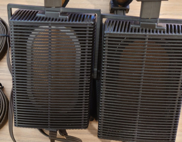
Two HS-0606-b heatsinks from PAR-METAL Click
HERE
Pick a size Par-Metal chassis that will fit. I suggest you buy all the parts first, and then collect them together on a desk and measure how large a space they require, and then order the appropriate size from Par-Metal in your favorite color. Click
HERE
You will also need:
TOOLS - power drill, files, screwdrivers, soldering pencil, small diagonal cutters or nippers, needlenose pliers
OTHER SUPPLIES - the thinnest 60/40 rosin-core solder you can find, some electrical tape to put around the bare AC line connections inside the amp, some misc screws and nuts etc.
To mount the heatsinks, place them over the ventilation slots in the chassis, and drill holes from the bottom of the chassis into the heat sinks, then use some sheet metal / self tapping screws to mount the heat sinks to the chassis. What you want is for air to be able to rise through the ventilation slots on the bottom of the chassis, pass over the fins of the heatsink, and then rise out of the vent slots on the top cover of the chassis. So you want to place the fins so that they have the most exposure to the vent holes possible given the space.
You can also find some fancier chassis on eBay that have heatsinks built in to their sides, if you prefer.
======Additions======
(Stuff I forgot)
5-way binding post output terminals - Parts Express - click
HERE
Hook up wire - I suggest using some 18 ga. Teflon insulated wire. Most hookup wire is 22 ga, but I think here you have a bit higher current on the DC side, so 18 ga might be a good choice. Probably OK to use 22 ga. wire from the AC power inlet to the on/off switch and from the switch to the primary of the power transformer, but I would use the heavier 18 ga wire for the power supply connections to the amp boards, and for the speaker output wires from the amp boards to the binding posts. Search eBay for some Teflon insulated wire, you don't need much, perhaps 5 feet. Teflon is best because the insulation doesn't melt or burn when you solder it.
You might want an LED pilot light, see Mouser
HERE
The power transformer I originally specified might be a little too small. This one from Mouser would be better, 30 V CT,
150 VA Click
HERE
=====Tips====
#1 TIP - DO NOT WORK ON THE AMPLIFIER WHEN IT IS PLUGGED IN TO THE POWER LINE!!!! Close the chassis up before plugging the thing in!
I suggest wiring the power supply first, without connecting it to the amp boards. The close the chassis up, plug the thing in and hit the power switch. If the pilot light LED lights up and stays lit, then disconnect the power cord, open the amp chassis up and wire the power supply to one channel at a time.....
The hardest part of this build will be cutting the rectangular hole in the chassis to mount the IEC power inlet/fuseholder. My suggestion for this is to make a cardboard template the proper size, and trace around it with a pencil onto the chassis where you want to mount the power cord. Now, drill the largest holes you can drill that fit inside the outline. After these are drilled, use a file or a chassis nibbling tool to enlarge and square the hole. (see
http://www.parts-express.com/nickel-plated-nibbling-tool--360-022 ) The AC power inlet is press-fit. You push it in to hole until the thing snaps in place.
This =>
http://makezine.com/2006/04/10/how-to-solder-resources/ is a soldering tutorial. Practice a little before you build, if you're not used to soldering.
In wiring the AC line, connect the hot lead from the AC input socket to the fuse and then to the power switch in series with the HOT lead going to the power transformer's primary; and don't forget to connect the power cord's safety ground wire to the chassis. See
http://www.ampmaker.com/pp-18-chassis-wiring-part-3-1043-0.html
The output transistors of the amplifiers need to be bolted to the heatsink, but the transistors must not make electrical contact with the aluminum metal of the heatsink- that's why you use the TO-220 mounting kits. ("TO-220" is the standard designation for this type of rectangular, tab-mount transistor) See
http://www.turkiyefagor.com/semi/pdf/rultiris.pdf for instruction on how to mount the transistors.
Note that this is a POWER AMP; if you want to add a volume control to it, I suggest a 50k audio-taper stereo pot like the Alps Blue Velvet, available on eBay for about $16 if you shop around ( like
THIS ) - and although the Blue Velvet has a reputation for quality, reliability and close channel balance, it is perfectly acceptable to use a less expensive pot like
THIS one from Parts Express for $2.40; you'll need some kind of knob for the volume control like
THIS budget one from Parts Express or
THIS nicely machined one from Mouser. ( or pick one out from
THIS selection guide from Mouser; be sure it will fit the 1/4" shaft of the volume control.)
HERE is a tutorial on how to wire the volume control.
You might want to get a book like
Circuitbuilding Do-It-Yourself For Dummies from your local library if you've never built any electronics. It's really not that hard to do, but there is a bit of craft involved.


")
