Basically all straight forward direct parts replacements, expect the step where you add high voltage reservoir caps. This class requires the least skills.
----* Caution! Always make sure the batteries are out and AC is not plugged in whe you work on the PCB. You don't want to get zapped by the 550v charge from the little transformer on the board.
---- This to-do list is for info purpose only, you assume all risk associated with the modification. I can not be held accountable for anything happens to you (whether good or bad).
A)Opamp upgrade –
* Desolder the stock in-line-8 super slow opamps. If you don’t have a desolder station with air pump, the easiest way to do this is by bending the opamp back and forth until all the leads break off the chip, then desolder the leads off the board, one lead at a time. There is no need to save the stock opamps, you will never want to go back to it.
* Clean up excessive solder around the holes, then solder the SOIC AD8599’s onto the existing pads on the board….
* Parts Cost: about $15.
B)+/- supply caps:
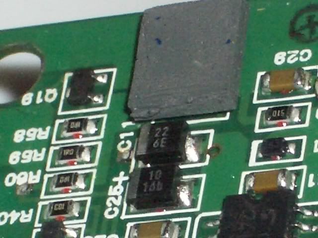
-- replace C17 and C18. Absolute largest size you can use is 6.5mm (dia)x 13mm(high). My recommendation is United-Chemicon SMG 220uf/16v, (digi-key # 565-1038). The reason for using SMG is because it has the highest ripple rating in all the miniature 220uf/16v’s (rated at 260mA. The KMG is 180mA, Nichicon VR at 220mA).
Another viable option here is United-Chemicon NPCAP 100uf/16V, digi-key # 565-3053-ND, $0.75 each. Though the capacity is smaller than the SMG, it makes up in speed, the ripple current rating is 2820mA (not at the same frequency as the SMG rating, but I’d bet it is still much much faster than the SMG’s) .
* Parts cost: $1 to $1.5
--Replace C27 and C28. The absolute largest size for these spots are 6.5mm (dia) x 8mm (h). The battery compartment reinforcement feature and contact wiring is in the way, so 8mm is about as high as you can go. Recommendation is Panasonic KA series 100uf/16v, (digi-key # P833-ND).
Parts cost: $0.30
-- You can also add four more caps directly from the opamps’ VCC/Vdd pins to the ground. I will leave that to you, since it requires a bit of improvising. The caps to use will definitely be the United-Chemicon NPCAP 100uf/16v. As a matter of fact, if you decide to use the 100uf NPCAP in C17/18 location, you will really want to add these extra caps to make up the total capacitance. Adding a small film cap in parallel with the electrolytic for high frequency by-passing is also a good idea.
Parts cost: 0 to $5 depending on how many NPCAP you use.
C) Short out R33/34/35. These were originally for forming a “pie” filter to clean up the +/- 12v supply, but the new opamps require a lot more current and these resistors create too much a voltage drop. Just add a piece of thin wire across the resistor ends and short them out.
D) Replace the C3’s (two of them) with 1uf tantalum capacitor. First desolder the stock cap, then solder the surface mount tantalum chips onto the pad (on the under side). You can use low ESR tantalum chip like digi-key # 478-2412-1-ND, value is 1uf/35v. The reason for using SMD parts here is to clear up space so you have more possible space for more high voltage reservoir caps.
-- parts cost: $2.5
E) Desolder C1 and C2’s (four total); Install BC MKP 0.12uf/63v polyprop’s at C1 locations (digi-key # BC2056-ND, $0.68 each) and add two dip tantalums at C2 locations. I have no idea which tantalum dip will sound better, get a few different ones and try them out. The max size to use is 6mm(dia)x 13mm(h), here are two that might work: Panasonic 33uf/10v (PA2029-ND) and KMET 33uf/10v (399-3576-ND), both are less than $1.5 each. If you insist on not using tantalums as input but don’t have boutique caps to use either….. well, Digi-key does have Elna “audio capacitors” –-- “ ELNA developed new raw material for the separate paper which uses a silk fiber. Therefore, this series can give high grade sound for any audio design. This series can
be used to relieve the music’s vibration energy, to decrease the peak feeling sound at high compass, rough quality sound at middle compass and to increase massive sound at low compass." (this is what it says on the digikey catalog).
Part # is 604-1051-ND, price is a whopping…. 15 cents each
-- parts cost: about $4.5, or less if you use Elna audio caps
F) Desolder C7 and C8’s (four total); Install BC MKP 0.011uf/630v caps (BC2240-ND). You can also use the larger values such as 0.016uf/630v, the physical size is the same as 0.011 caps, it probably won’t make any sonic difference when driving the SR-001. (But larger value will give better bass if you do end up using an adaptor cable to drive the small pro-bias phones like Gama Pro or SRX pro).
-- parts cost: about $3
G) * Caution! Always make sure the batteries are out and AC is not plugged in whe you work on the PCB. Exercise extreme caution when wiring the high voltage caps since one mis-connection can fry the amp, the opamp stage will not survive a 550v hit.
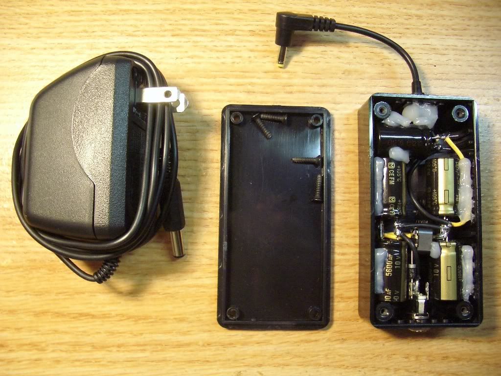
--Desolder C6; Add two pieces of wires to a 0.1uf/630v X2 cap’s leads (digikey # 496-1881-ND, $0.48 each) then solder the cap into the board. The purpose of the wires is for paralleling more 0.1uf/630v X2 caps to it. You might also want to order some 496-2319-ND, it is also 0.1uf/630v ($0.32 each) but is thinner and longer; having two different size caps will help you utilize whatever room is available inside the case. This requires you to improvise though. I will recommend ordering 3~5 of each part # just in case.
You will want to pack in at least 0.3uf total (can easily be done), but there is no need to go higher than 0.8uf. Fix down the extra reservoir caps with hot glue (the good thing about hot glue is it hardens right a way, won’t smear, and if necessary, easier to get rid of later)
-- parts cost: anywhere from $3 to $5.
H) Add a good electrolytic cap between ground and DC input + (after the switch). There are no existing holes/spots for you to do this, so I will leave this up to you. A good cap aross the DC power input can make quite some improvements in bass texture presentation. Or you can build an external power conditioning box (actually a cap box), but that will be before the switch and will not be as effective. More on the cap box later.
By doing these mods you will increased the opamp’s speed by 50 time, high voltage reserve by 30 to 50 times, and +/- reserve by 10 to 30 times (which is required by the faster opamp, so you don’t really have a choice here
). All parts can be ordered from digi-key, total parts cost will be less than $40. Shipping/tax will likely be around $10, so < $50 all together.
-- Skill level required: if it wasn't for the Stax high temp (silver?) solder, I'd say it is a bit easier than building even the simplyest perf board Cmoy. At here you don't do wiring (except the paralleling more caps to X2 high voltage power reserve part), just replacing parts.
-- Total time to complete the FatCat class mods: anywhere from 45 minutes to 4 hours (from opening the case to closing the case), depending on your equipment and skill level. I can finish one within 45 minutes since I have access to an air pump desolder station, though I don’t see everybody using a station like that (the PACE 250 is more or less a $1200 machine). The mod is fully doable with just a pair of diagonal cutters, a pencil soldering iron, and a hot glue gun, less tool requirement than making a Altoids Cmoy.
If in doubt, go slow….. will be a fun little Sunday afternoon project.