The LCDuino-1 I/O processor
Sep 30, 2009 at 3:32 AM Post #61 of 403
a demo build:

3968132890_356dd9bb78_o.jpg


3967356347_200a264b4a_o.jpg


3968131918_2241814732_o.jpg


the blue electro cap is a bit taller than I wanted. next time I'll use a smaller one and the sandwich will fit a bit more snugly.

the 3 color ribbon wire is going to my PGA chip board (chip-select, clock and data).
 
Sep 30, 2009 at 3:53 AM Post #62 of 403
detail on how to mount the supercap (battery backup for clock chip):

3968179220_9aa8f54751_o.jpg


its soldered across ground and the trickle-charge pin. how nice that each pin is at diagonal ends of the chip and that the supercap fits just perfectly in place, there
wink.gif


if you don't care about having a clock or battery/cap backup, this can be omitted; but its really nice to be able to set your clock once and not worry about short-term power outages (I've seen it last for half a week on its own capacitor, so far.)

its a .022F (farad) cap at 5.5v.
 
Sep 30, 2009 at 4:37 AM Post #65 of 403
Quote:

Originally Posted by Dougie085 /img/forum/go_quote.gif
So can you put a bigger LCD on this? Or is that just that ethernet thing?


Yes, a 4x20 LCD module will also be pin-compatible with LCDuino-1. The LCD will be larger than LCDuino-1, and the four mounting holes won't line-up, but it will work. Of course the firmware will need to "know" to take advantage of the extra width and rows.

We are currently focused on the 2x16 LCD module to avoid taking the project in too many directions at the same time (and with all the planned "app modules" we really have to keep from spreading ourselves too thin). Also the 2x16 LCD module is sufficient for most uses, and will fit in slimmer/smaller cases.
 
Sep 30, 2009 at 4:37 AM Post #66 of 403
Quote:

Originally Posted by Dougie085 /img/forum/go_quote.gif
So can you put a bigger LCD on this? Or is that just that ethernet thing?


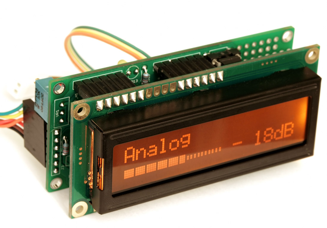
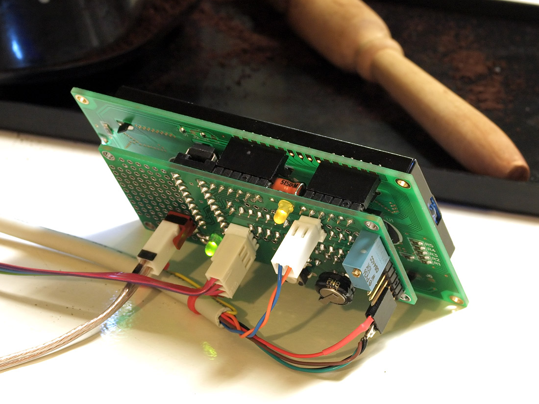
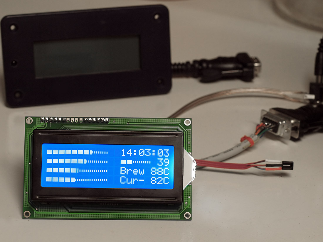
I can show a photo with that backpack board on a larger 4x20 style display.

it works. I tested that, first, since I had one handy at the time
wink.gif
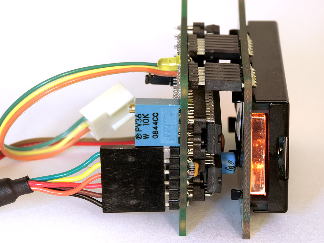
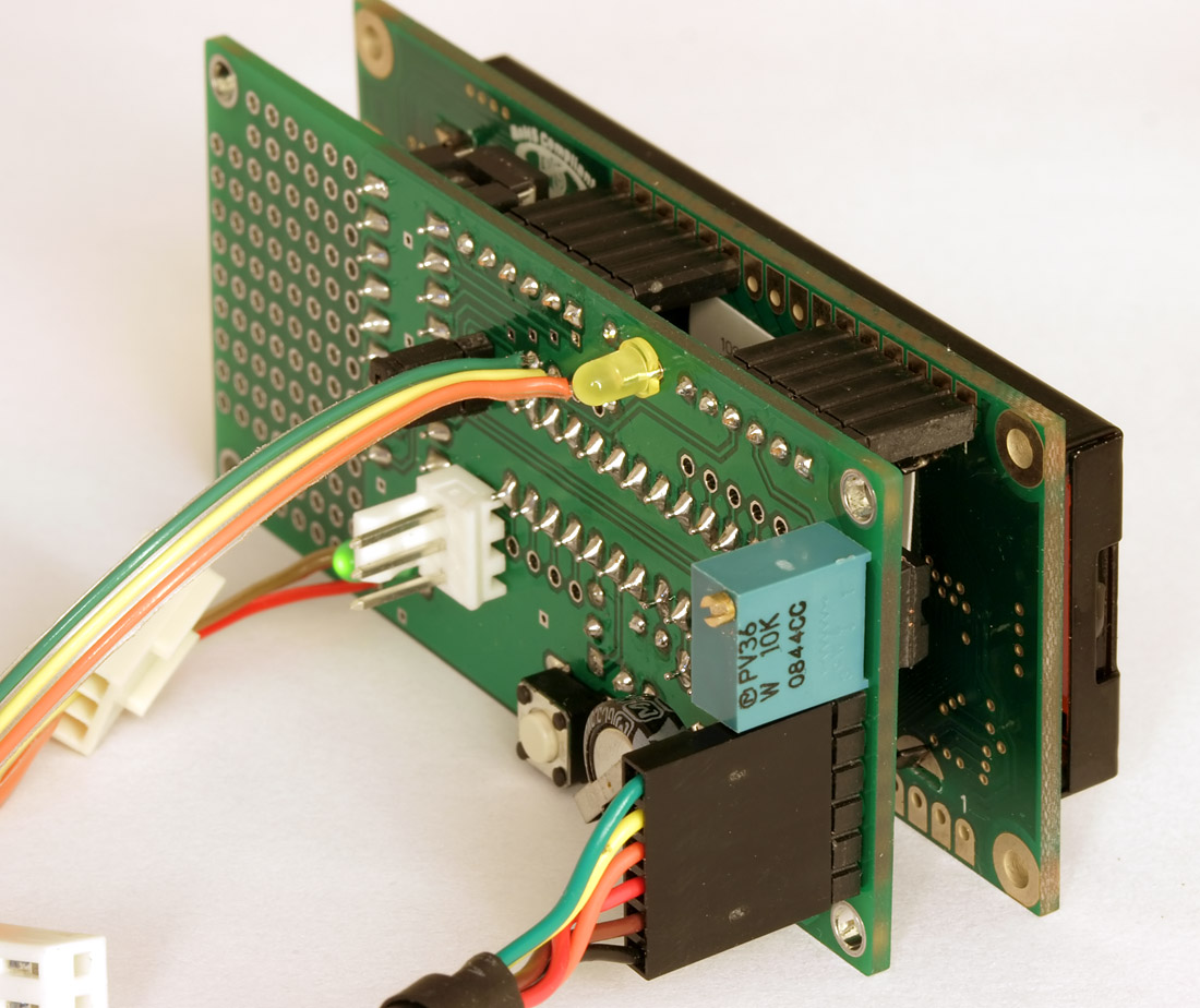
its just that it doesn't mount directly to the lcd via screw holes; it had to be held on *only* by the tension of the pins and headers. but for me, I'd be ok with that. the lcd unit, itself, has to be bolted to the front panel; but the backpack board can hang on by the pins and probably be fine in most cases on just that.

software wise, you address each line by a magic constant and you have 'x' amount of chars to use before things go into no-man's land
wink.gif
I keep things simple, print at line 1 or 2 or 3 or 4 and on the larger displays, you have 20 chars per line. on the smaller ones, you have 16. when I create a program (or 'sketch' as the arduino guys like to call programs) I usually specify at the top what the display is going to be (16 or 20 chars). and the app I write will be very specific and designed with placements all setup for *that* kind of display.

but, if something works on 16x2 displays (ie, the code is written for that) then it will also work as-is on the 20x4 ones. the reverse is not true, of course
wink.gif


I'll take a photo of the backpack on the 4x20 board later on. but they do work and you can address all 4 lines via software pretty easily.
 
Sep 30, 2009 at 5:18 AM Post #68 of 403
I have not used or found any simulator. have not searched for one, though, to be honest.

to play around, you only need a base arduino board (many sources for that), the port expander chip and a standard hitachi style lcd. its breadboardable so simulators really don't make sense to me, with such simple hardware.

there is nothing timing critical about the lcd and cpu path. so even if your resonator is mounted on breadboard, I bet things will still work ok. wiring is not really critical here, from what I've seen.

if you can breadboard the thing in an evening, why even bother with a simulator?
wink.gif
 
Sep 30, 2009 at 6:09 AM Post #70 of 403
Quote:

Originally Posted by _atari_ /img/forum/go_quote.gif
BTW: @linuxworks - I think it is time to feature this on MAKE.


agreed
wink.gif


it has been there, on the 'blog' section:

Make: Online : DIY Arduino LCD backpack

but didn't feel it was ready until it had a PCB and some more testing.

perhaps after beta test would be a good time to do a MAKE mag. submission?

the SPDIFmaster switch was also in hack-a-day (grin) and that used the same basic backpack, as well.

I probably have 4 or 5 of those backpacks around the house doing various things. some audio, some coffee, some neither
wink.gif
it seems a very useful combination of things to have on a single board and I'm glad I won't have to rely on the perfboards for too much longer
wink.gif
 
Sep 30, 2009 at 6:37 AM Post #72 of 403
Quote:

Originally Posted by _atari_ /img/forum/go_quote.gif
Welcome AMB in the world of microcontroller


Thanks!
smily_headphones1.gif

I didn't get into the microcontroller thing just for the sake of it, but because it offers opportunities for better audio. It also lets me branch out into new areas of development that happens to be exciting and
cool.gif
.
 
Sep 30, 2009 at 6:52 AM Post #73 of 403
Quote:

Originally Posted by amb /img/forum/go_quote.gif
Thanks!
smily_headphones1.gif

I didn't get into the microcontroller thing just for the sake of it, but because it offers opportunities for better audio. It also lets me branch out into new areas of development that happens to be exciting and
cool.gif
.


Yes, it is nice to create physical objects with complex behaviour. Microcontrollers are very haptic for me.

Let's see how my remote control will work out.

The timing of your project is perfect. Since my amp at home failed and now I need a DAC, preamp and amp - but you have probably seen my other thread already.
 

Users who are viewing this thread

Back
Top