The LCDuino-1 I/O processor
Mar 1, 2010 at 3:49 AM Post #271 of 403
Voltage sensing and auto/manual biasing tool anyone? You'll never have to open up your casing again. This is starting to look like the most versatile project ever!
 
Mar 1, 2010 at 3:56 AM Post #272 of 403
that idea has been raised a few times
wink.gif
I personally like it. when I've had to tweak pots and watch meters, I thought to myself 'shouldn't a robot be doing this instead, and perhaps even monitoring it and allowing front-panel control of it?'

servos do this without 'processing' but what if the circuit is not already designed to support this and you want some 'tuning module' as an option or accessory?

yes, I think its a neat idea and good application of a control platform.
 
Mar 1, 2010 at 4:47 AM Post #273 of 403
Quote:

Originally Posted by linuxworks /img/forum/go_quote.gif
Juaquin got my intention 100%. thanks, mate.


ahhh. i see... heh.

Back in the good old days we didn't have microcontrollers and used these things called "servos" to do this type of stuff
smily_headphones1.gif
 
Mar 1, 2010 at 4:57 AM Post #274 of 403
like I said, servos are the conventional way. but what if you wanted to build in some rules or do fancy things that might need software assist? it might be nice to control time constants or even follow different rules for letting something warm up and then step into a different 'curve' for keeping it at some bias point. with a software component, you can at least try different things out and not have to solder or buy new parts
wink.gif


perhaps the controller can make use of multiple kinds of input: the current rail voltage or temperature or other variables and use that in making its decision. normal servos can't be that smart but controllers can.

I wouldn't dismiss controllers are being 'overkill'. we like that here in DIY, don't we?
wink.gif
 
Mar 1, 2010 at 4:59 AM Post #275 of 403
Quote:

Originally Posted by linuxworks /img/forum/go_quote.gif
if I understand you correctly, you want to use the lcduino1 as the controller but have it talk to your own board?

its open-source and so yes, you should be able to 'software glue' your board to the lcduino1. if you use i2c it might be easier (as there will be examples to follow, to speed your customization).

what you would do is to find the action routines (when the user presses 'input button 1', say) and then call your routine instead of the built-in one. like that.


Basically.

Quote:

Originally Posted by luvdunhill /img/forum/go_quote.gif
Chris, I'd expect that you'd need more circuity on your board that what you mentioned. (Perhaps you didn't give an exhaustive list?) For example, do you plan on having relay driver on the board and control mechanism as well?


I am just starting to determine whether this is a path I want to go down or not, so no, I haven't defined what is on the board beyond the jacks and relays. Since it will be a vertical back panel-mounted board, I don't have a ton of real estate to work with, so it may have to interface another board to interface to the controller.

Is there any website with more detail on the this project? I have done machine language/assembly language programming before, but haven't played around with anything for several years now
rolleyes.gif
 
Mar 1, 2010 at 5:07 AM Post #276 of 403
Quote:

Originally Posted by Pars /img/forum/go_quote.gif
I don't have a ton of real estate to work with, so it may have to interface another board to interface to the controller


Perhaps this is derailing this thread a bit, but I think you might at minimum want a relay driver. I have used a QFN package for this that is quite compact and I'd look at some of these type packages personally.Perhaps LinuxWorks has some recommendations as well. You might also want to talk with Jacob, as I think he's done a layout for something like this as well (vertical, etc.), and found that 4-layer board simplified things greatly.
 
Mar 1, 2010 at 5:14 AM Post #277 of 403
I would suggest having an i2c decoder on your board and bit-mapping the relays. its just an array of relays; what they do doesn't matter as much. the 'handover' from the arduino controller to your board would be, I would think, i2c and you just have to define the 'application protocol' so that the controller and the i2c slave will speak the same semantics. ie, when the controller turns on bit 3, say, of the 8bit byte, what does bit 3 mean when you receive it on the target board side? it might mean to mute the main muting relay or it might mean turn on input 2 to the 'audio bus'.

you'd define an interface (like a .h file) and then those defines would be used in both your hardware (so to speak, via pc traces) and on the controller side via custom 'driver' software.

the glue comes in where you 'bind' the keypress (button X on a remote) to the abstract event you want to happen on the target board (latch bit 3, whatever that does on the hardware) and like that.

that's kind of the broad overview of how I'd approach it. bit-map the 8 available bits (assuming you can fit all your 'states' into 8 bits) to some native board function and then flip those bits under software control when user events occur (button presses on remotes or front panels).

if you use non-latching relays, its a lot easier and you just resend the 8 bits each time any one of them changes (i2c means you can't send just a bit or two; you are committed to 8 bits for each 'message' to the target board).

the mcp controller that we used for the lcd interface could be used and you could use the lcduino1 schematic for the mcp connections. give your mcp chip a new 3bit address and put that chip on your board. connect your board to the common i2c bus and be sure to reference the right i2c address when sending byte mask (relay mask) updates.
 
Mar 8, 2010 at 12:48 AM Post #278 of 403
progress on the relay controller side of things:


4415601314_62889b36cd_o.jpg


4414845493_acaa6db8c7_o.jpg


it consists of 2 port expanders (i2c serial), 2 relay driver chips (ULN2803), 2 resistor SIPs (for relay 'bias' and led current limit) and 2 LED bargraph 'debug' displays.

I also wrote a short C program that will calculate the R values needed for the R-2R ladder attenuator. here's a first version:

Index of /audio/r_2r_calc

a sample run:


% make
cc -c r2r.c
cc -o r2r r2r.o -lm

% ./r2r 8 0.5 25000
using bits=[8] stepsize=[0.5] z=[25000]
max_atten=[127.5]
bit 0 db -0.5 Rs=[1398.5] Rp=[421914.4]
bit 1 db -1.0 Rs=[2718.7] Rp=[204887.0]
bit 2 db -2.0 Rs=[5141.8] Rp=[96552.9]
bit 3 db -4.0 Rs=[9226.1] Rp=[42742.8]
bit 4 db -8.0 Rs=[15047.3] Rp=[16535.6]
bit 5 db -16.0 Rs=[21037.8] Rp=[4708.5]
bit 6 db -32.0 Rs=[24372.0] Rp=[644.2]
bit 7 db -64.0 Rs=[24984.2] Rp=[15.8]

I gave it 8 bits (8 relays), 25k as an output-z and 1/2dB as the native step-size. Rs is the series R and Rp is the parallel (shunt) R.

the new volumaster LCDuino1 firmware will be able to take, from the user, the 2 key parms (# of relays installed, step size) and it will 'do the right thing' when talking to the relay controller.

so, in theory, you could populate the 8-relay board with just 6 relays (if you wanted to) and space them .1 dB apart, such as this:

% ./r2r 6 0.1 25000
using bits=[6] stepsize=[0.1] z=[25000]
max_atten=[6.3]
bit 0 db -0.1 Rs=[286.2] Rp=[2158996.4]
bit 1 db -0.2 Rs=[569.1] Rp=[1073284.2]
bit 2 db -0.4 Rs=[1125.2] Rp=[530464.0]
bit 3 db -0.8 Rs=[2199.7] Rp=[259125.9]
bit 4 db -1.6 Rs=[4205.9] Rp=[123600.6]
bit 5 db -3.2 Rs=[7704.2] Rp=[56124.3]

and that would be the 6 R value pairs to use and you'd get just over 6dB of atten but down to the 0.1db level. if you wanted...
wink.gif


as long as the board matches the software (you enter those things to the software on the LCDuino1) then it will work.

most people will probably go for 8 bits and .5db as the spacing, but you CAN do whatever you want, here.
 
Mar 8, 2010 at 1:48 AM Post #279 of 403
linuxworks,
thanks for the post. very helpful
wink.gif
.
 
Mar 8, 2010 at 5:30 PM Post #280 of 403
Quote:

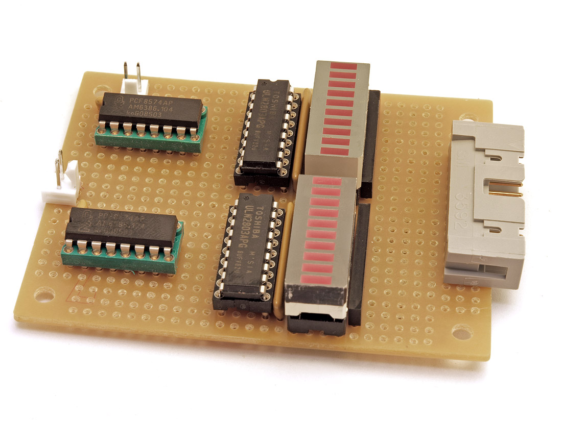
Originally Posted by jtostenr /img/forum/go_quote.gif
Are the bargraph leds there only for development, or are they going to be on the production board as well?


yes, we're planning on having board space there (and resistor networks) for people to populate. there are many sources for these bargraph chips (isolated non-bused led segments) and they're cheap and useful to debug things. so we're planning to have them on the production board.

the firmware will have some 'demo' modes so you can see the firing sequence and also some true debug modes that will let you latch on and off each of the relays, so you can see if any of them are stuck or broken (initially or even over time). being able to see the lights could be useful in that pursuit.

there will be a jumper (hard jumper or switch) to electrically disconnect them at will and stop the light show
wink.gif


normally they're off, anyway; on end is sitting close to + and the other end gets temporarily shorted to gnd to 'signal' a pulse to one side of the relay or the other. if side A, then that bank of leds will have lights turn on; and if side B of the relay wire, then the flash comes from the other bargraph chip. the pulse time is very short and so the lights will look like they're off most of the time and only when you turn the knob or use the IR remote will there be a short burst of 'run-up' and some light activity, then they will all look off again after run-up is over. its only when you run it in 1/100 speed (or like that) that you'll see the individual leds fire.
 
Mar 8, 2010 at 11:58 PM Post #281 of 403
Quote:

Originally Posted by linuxworks /img/forum/go_quote.gif
there will be a jumper (hard jumper or switch) to electrically disconnect them at will and stop the light show
wink.gif


What if I want a light show? I'm mounting mine on the front panel baby!
very_evil_smiley.gif
 
Mar 9, 2010 at 12:05 AM Post #282 of 403
during normal operation, the lights won't even be visible to get much of a show. the flashing would be over in mere milliseconds.

if you run debug mode and stretch the timing your volume control events are blocked until all the bits are clocked out to the i2c serial bus. it could take a few seconds to display all the led flashes and no one would want to wait that long before being able to click up or down to the next volume level.

the leds directly show the voltage pulses to the relays; so when you run in debug mode, you are holding voltage high for 'that long' while you display and pause on the led. just something to realize when you are playing around; and that these relays are meant to have current sent thru them, then STOPPED very shortly afterwards.
 
Mar 9, 2010 at 2:01 AM Post #284 of 403
these LEDs would not be good for a 'non debug' show.

but nothing says you could not use the very same idea and give it a new i2c addr, then update the firmware to send pretty patterns or VU simulated levels (?) to such displays. as long as you don't take too much of a time slice (inside the big do-loop); things are kept simple, right now, and almost nothing is interrupt driven. if any one task takes too much time, the others are blocked until it gets around to them.
 
Mar 11, 2010 at 1:11 AM Post #285 of 403
a heads-up for the home theater guys here. there's an hdmi switch (3 ports) on sale today for $15:

Meritline.com - HDMI v1.3 + HDCP 3 Ports Mini Switch, intelligent Auto Switch and 3 pcs of 6 Feet HDMI v1.3 Male to Male Digital A/V Cable, 30 AWG Cable, Category 2 Certified, Support 1080P HD Resolution

195-119.jpg


what caught my interest was that it has a remote IR input for picking the hdmi port that gets selected. IR is just TTL signaling and the arduino can easily learn and repeat IR commands. this means that, in theory, we could have this hdmi switch 'slave' to whatever spdif channel the user selects via the lcduino. this box would sit in the back of your a/v shelf and the hdmi cables would run to this; then a single cable would run from the hdmi box to your spdif/lcduino box. you'd setup the association of which spdif port goes with which hdmi port.

for this price, I'll give this hdmi switch a try and see if its as remote-able as I think it may be.
 

Users who are viewing this thread

Back
Top