The GrubDAC
Apr 8, 2010 at 12:38 AM Post #271 of 1,079
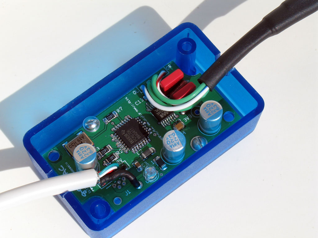
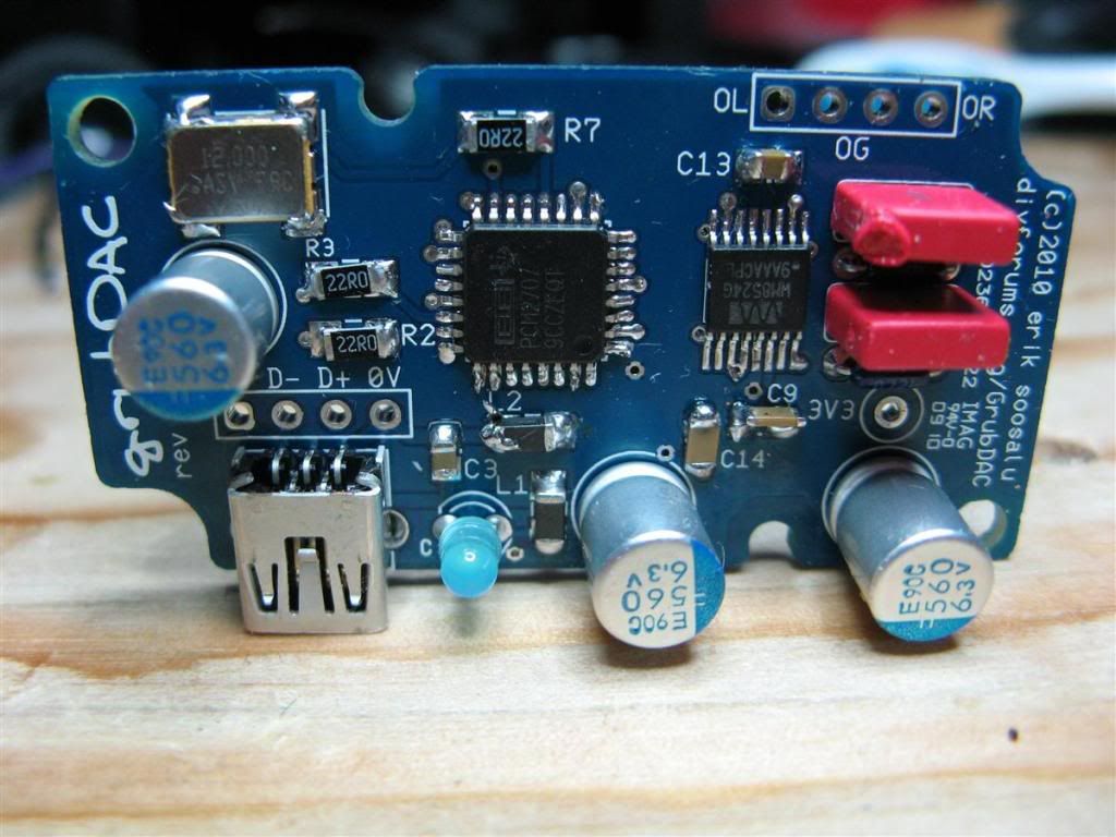
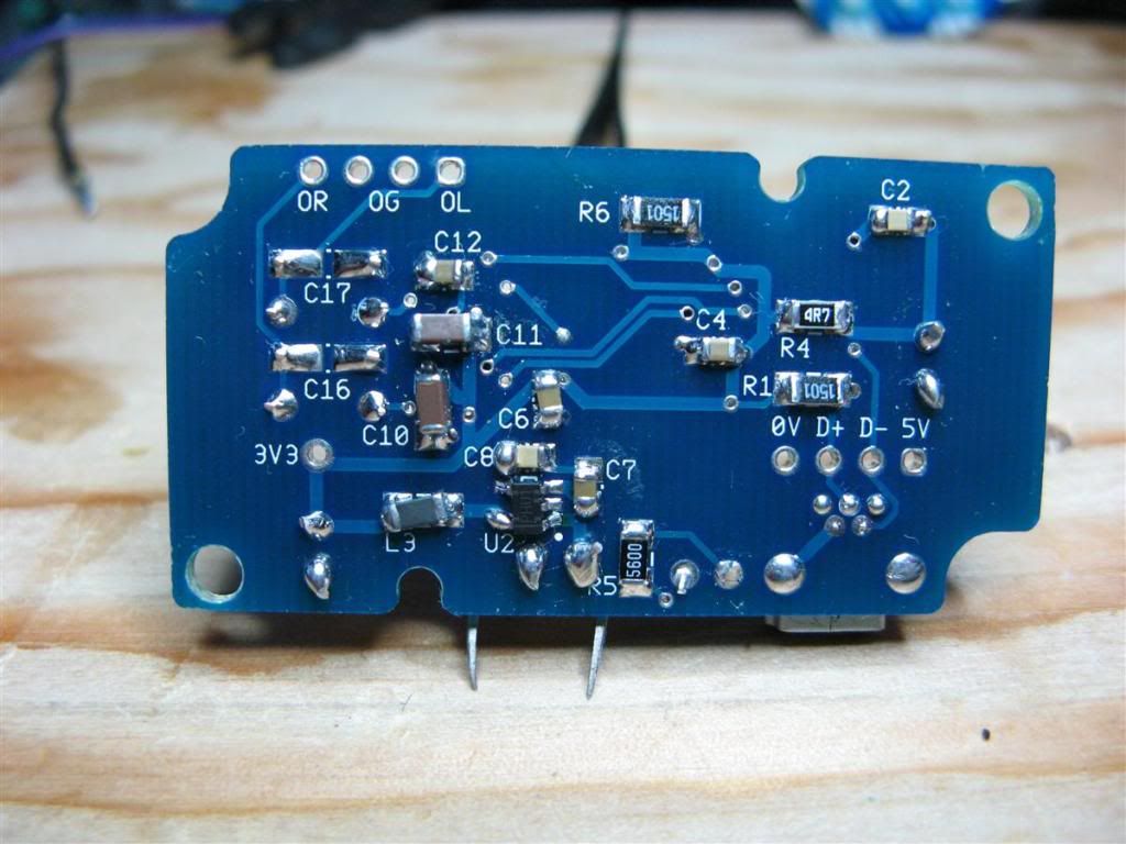
Can someone supply a finished picture of their production board with the components installed. I recently finished mine and connected it to the PC to make sure it powered up and was recognized before swapping the Bantam out of the MOSFET MAX. The board powered but windows 7 doesn't recognize it. I had doubts on the the orientation of the Wolfson (U3) and the Osillator (X1)

Right about now TomB is shaking his head ...
icon10.gif
 
Apr 8, 2010 at 2:14 AM Post #273 of 1,079
Thanks cobalt ... mine appears to be correct except I've installed the mini USB (and my soldering's much neater! {just kidding, Tom's witnessed my "handywork"}
rolleyes.gif
)

I've reflowed a few smd's after reading the posts here and checked for coldjoints & bridges but everything looks ok. LED is lit, nothing's warm or hot to the touch. I'll keep digging. maybe put another together in the meantime but if you have a list of checks I could use one.
I will be building a total of three, one for the MAX, one with RCA's and another in a yet to be decided configuration.

I noticed alot of "spare" thru holes, do I need to jump anything?
Catch up with me at your earliest convenience.

Thanks in advance,
Jay R.
 
Apr 8, 2010 at 5:16 AM Post #274 of 1,079
Sorry you're having troubles, Jay. There's a lot I still need to do to update the grubDAC website. I don't think this pic is actually up there right now. This is a closeup pic of one of the two I built - the PCB should be identical to the production PCB except the notches on the corners of the production PCB are slightly smaller and the production PCB is blue:


[size=xx-small](click for a bigger pic)[/size]
 
Apr 8, 2010 at 12:51 PM Post #275 of 1,079
Quote:

Originally Posted by ovrclkd /img/forum/go_quote.gif
I've reflowed a few smd's after reading the posts here and checked for coldjoints & bridges but everything looks ok. LED is lit, nothing's warm or hot to the touch. I'll keep digging. maybe put another together in the meantime but if you have a list of checks I could use one.
I will be building a total of three, one for the MAX, one with RCA's and another in a yet to be decided configuration.


What voltage are you getting on the 3V3 point? This is the output of the voltage regulator. The LED is powered straight off the USB bus with no regulation.
Quote:

I noticed alot of "spare" thru holes, do I need to jump anything?
Catch up with me at your earliest convenience.


Define a lot. If you have a mini-USB build, you should have 4 holes next to the USB jack and the 3v3 test point. You may also have holes for C16 and C17 if you used the surface mount alternative. Other "holes" should be very small vias from the top to the bottom of the board.

Pictures maybe?
 
Apr 8, 2010 at 11:32 PM Post #276 of 1,079
Quote:

Originally Posted by cobaltmute /img/forum/go_quote.gif
What voltage are you getting on the 3V3 point? This is the output of the voltage regulator. The LED is powered straight off the USB bus with no regulation.


No Voltage at 3V3 .... short somewhere?


Quote:

Define a lot. If you have a mini-USB build, you should have 4 holes next to the USB jack and the 3v3 test point. You may also have holes for C16 and C17 if you used the surface mount alternative. Other "holes" should be very small vias from the top to the bottom of the board.

Pictures maybe?


I was looking at the vias holes, must be a dozen or so... here's some pix, maybe something will jump out to the trained eye.
icon10.gif

You'll see I chose to mount C9 vertically when I reflowed it due to lack of room.
Thanks for your help! Please excuse my solder skills ... I'm still learning!
redface.gif


IMG_1782.jpg


IMG_1781.jpg
 
Apr 9, 2010 at 2:23 AM Post #277 of 1,079
hey all so i am building my grubdac.. however, when i plug it in i am geting usb device not recognized.
my led lights up and i'm getting 3.3v at the test point..
i could swear that there are no solder bridges on my chips.. but here are some pics of the board.. does anything seem amiss?? Photo Albums - Imgur
 
Apr 9, 2010 at 2:43 AM Post #278 of 1,079
ovrclkd, Your L3 looks a little weird. Can you check the resistance across it? It seems different than L1 and L2. You C9 and C14 also look a little different. I would suggest that you get used to using a lot less solder. There is a lot of blobs.

particleman, The pics around both the PCM2707 and WM8524 aren't clear enough for me to pic up anything.

I would advise that both of you go over your board with a good magnifying loupe. I personally use one of these. You'd be amazed at what you see under magnification.
 
Apr 9, 2010 at 4:07 AM Post #282 of 1,079
Quote:

Originally Posted by particleman14 /img/forum/go_quote.gif
after checking my 2 chips.. I am now about 95% convinced there are no solder bridges.. i even resoldered each pin again just to make sure... any suggestions I should try??


IMO double check all your passive SMD components. Several of them look questionable. Especially R2 R7 C14 and L2 (possible solder bridge across the top?).

While you're at it, see if you can get rid of any solder spikes by reflowing the solder joint(s) with a bit of flux. Solder spikes can introduce unwanted EMI/RFI into the circuit.

If you still have problems, check the datasheet for both the TI and Wolfson ICs regarding maximum soldering duration and temperature for the pins. It's possible one of the ICs could have been damaged due to heat. I'll assume you followed safe ESD practices when handling the chips.

Hope this helps.
 
Apr 9, 2010 at 6:23 AM Post #283 of 1,079
If you want to be 98% sure of solder bridges, get a high powered (preferably LED) flashlight and shine it through the board from the back side. I'm not sure about the Grub but with the Bantam it made solder bridges very obvious.
 
Apr 9, 2010 at 8:22 AM Post #284 of 1,079
ya used the light to help look for bridges. still can't see any.. however, I refluxed and heated all my joints and still no dice. I am scared that perhaps i maybe fried my one of the chips.. will post up more pics after ive cleaned flux.
 
Apr 9, 2010 at 8:49 AM Post #285 of 1,079
Yeah, it happens. Especially if this is your first SMD work. I fried a couple Bantams before I finally got one right. If only these DAC chips came in through-hole DIP packages - I'm sure there would be a lot less frustration in the world.
 

Users who are viewing this thread

Back
Top