Why DO power cables and such make ANY difference to our headphone gear?
Yet another experiment focusing on power delivery and some not generally understood factors to consider.
Part A Why Would I Want To Do This In The First Place?
https://www.head-fi.org/threads/the-diyrs-cookbook.781268/page-85#post-14294952
Part 1 Theory and Expectations Based Upon My Initial Research
https://www.head-fi.org/threads/the-diyrs-cookbook.781268/page-89#post-14593223
Part 2 Measured Results and Observations.
Part 3 Analysis and Conclusions.
Part 2 Measured Results and Observations
But first a Re-Cap.
Bits are bits, wire is wire and as long as the music plays there should be enough voltage and current, so what’s the problem, right?
And especially with our HP gear that uses so little power to begin with, as such, ac power cables should make no difference right?
I mean a 9w/ch amp driving high Ω HP’s there should be no effect when trying different power cables.
Except that that isn’t what I heard…
This was a challenge to try and figure out.
And now,
Part 2 Measured Results and Observations
I’ll include a few oscilloscope pictures of the voltage and current wave forms super imposed upon each other to show when the current starts and stops flowing in relation to the voltage swing.
What I’ve measured and now present is an approximation of the time and amounts of voltage and current that is shown by the scope.
In addition I’ll provide some insights into the dynamics of this relatively static picture.
I call it a static picture because these measurements were taken while the amp is idling and no signal (music nor fixed test tones) are being amplified, and these wave forms don’t change.
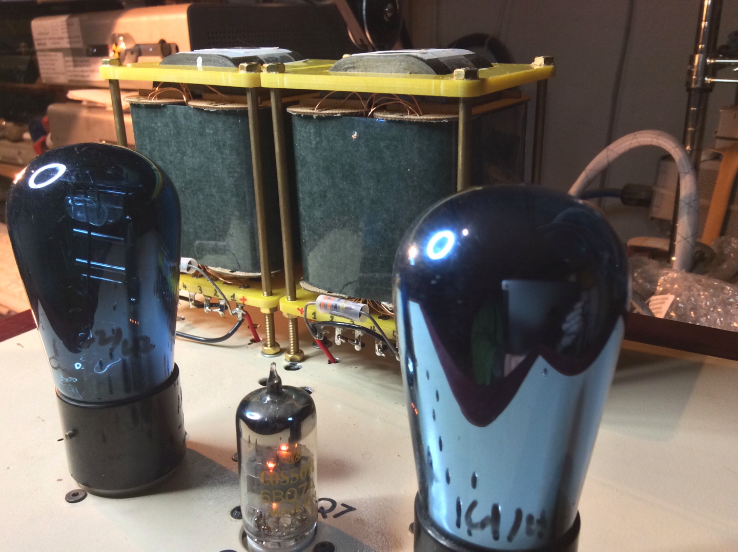
Now these pics of the measurements were taken using my Tek 468 O’scope and an Aim iprober 520 contact current probe by my ipad.
I volunteered my Schiit Mojo amp (1st gen) as test bed for these experiments.
It is rated at a maximum of 45watts of power consumption and delivers 8watts into 32Ω, (or 32watts into 8Ω which it isn’t rated to do, but is a relative gauge).
And operates with 2 watts in class A operation as it’s normal bias for each channel, at idle.
These measurements were taken with no input (& the volume control is all the way down) nor is there any load on the output.
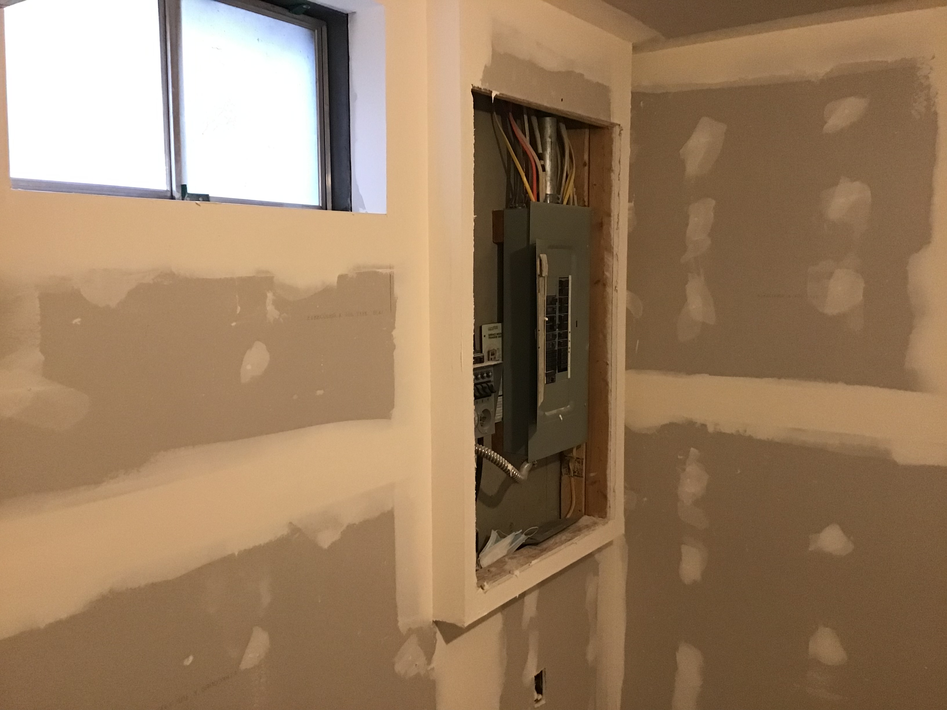
The location where the measurements were made was at the ‘output’ side of the fuse holder, after the switch and before any of the rest of the power supply.
The Aim iprober is a direct contact current probe, meaning it reads the magnetic field at the circuit board trace, and then uses the O’scope to display the wave form shape.
As such it does not add any additional load nor does it limit or affect the current pulses.
pic of setup with arm and probe

Notice the voltage probe ‘seeing’ the voltage that the current probe is measuring at the same location and at the same time.
And since it is a contact probe and isn’t a direct measurement of the current flow, placement becomes a variable in taking measurements. This is why I am using approximate numbers and amounts.
Plus exact numbers aren’t really necessary at this point in these investigations.
I’m looking for ‘Big Picture’ views and not focusing in, nor drilling down onto, the specific details themselves.
It turns out that while operating at idle, in those ≈ 8+ms windows of time, current passes in ≈ 3+ms slices of time, followed by ≈ 5+ms of being off, followed again by a ≈ 3+ms ‘ON’ window of time.
This means that the current actually flows for only ≈ 37% of the available time, into the downstream power supply.
pic power pulse V&I

And in that ≈ 3+ms of time, the amount of current that I measured is ≈ 0.4amps(PtP) in a peak time window of ≈ 1+ms.
This means that in one full cycle of 60Hz the peak current delivered is ≈ 0.8 amps(PtP) during two ≈ 1+ms peak windows, and all current flows in 2x ≈ 3+ms windows for each full cycle.
pic power pulses I PtP

Now, a peak 45watt load needs ≈ 0.375amps on a 120v supply voltage, in a 100% duty cycle environment with a symmetric periodic wave form.
Huh? (I can hear you respond…)
100% duty cycle means the current flows continually (like a battery) with no stops nor starts. So a 50% duty cycle means the current flows for 50% of the time and doesn’t for the other 50%. And in this case has a ‘rep rate’ of 60/sec or 60Hz.
And the symmetric periodic wave form (sine wave) means there is symmetry to the flow of voltage and current.
But the Mojo amp, at idle, is operating in a ≈ 37% duty cycle which means that if our peak 0.8amps(PtP) were scaled up to 100% duty cycle. the current would be equivalent to ≈ 2.1 amps or a 267% difference, to the added time that current flows.
As was mentioned this is an expected result for the need for current (power) but with a limited amount of time to deliver that power.
Which in turn means the power comes into the downstream storage / filtering / regulation portion of the power supply in a series of ≈ 3+ms pulses followed by ≈ 5+ms of ‘off’ time.
So in effect in this light duty situation while driving a ≈18watt amplifier, the amp is ‘asking for’ peak current flow of 0.8amps(PtP) yet a 18watt load should only need 0.17 amps if it were a 100% duty cycle.
This represents a 470% increase in the amount of current from a ≈37% duty cycle vs a 100% duty cycle, and assuming the current flows in a symmetric waveform (which it doesn’t because it’s asymmetric, see below).
IOW these pulses are best thought of as short, sharp ‘demands’ for instantaneous current flow. Followed by longer duration ‘off’ times.
And not, steady, even amounts, of uniform, symmetric periodic current flow, as many might think.
end Part 2
Next up
Part 3 Analysis and Conclusions.
JJ


") hahahahahahahahahahahahaha
hahahahahahahahahahahahaha


