The HD-800 a headphone ahead of its time.
And the ‘need’ for modifications, common assumptions, and my different approach and results.
Part 1
https://www.head-fi.org/threads/the-diyrs-cookbook.781268/page-84#post-14269778
Part 2
https://www.head-fi.org/threads/the-diyrs-cookbook.781268/page-87#post-14447507
Part 3
So first off let me repeat…
DANGER!!! DANGER!!!!
YOUNG WILL ROBINSON
DANGER!!!!!!!!!!!
So this modification project has a few caveats and among them is…
We are fussing with the basic design of the 800’s and as such there is NO BACKUP, NO SAFETY NET of ANY kind!
DO this at YOUR OWN RISK!!!!!!
This will VOID your Warranty!!!!!!!!!!
If you screw up there is NO BACKUP other than yourself!!!!!!!!!!!
While repair parts are available they can be expensive (a set of drivers costs ≈$240 +S&H) and are usually backordered to Germany, think weeks)!!!!!!!!!!!!
IOW this modification requires a degree of commitment and responsibility on the owners part to assume ALL RESPONSIBILITY for the implementation of these mods.
Caveat Emptor!
I just want to make this clear that this is not a beginners modification, is NOT easy for those who are not good with tools, their hands, and know how to handle delicate pieces and parts that make up a headphone.
This is a true DIY project with minimal instructions/guidelines, because typing out all of the details involved just isn’t going to happen. It would turn into an encyclopedia, and I’d rather spend my time tweaking and not writing out those myriad of details.
So be forewarned this is a complicated and involved series of modifications that an experienced DIY’r will know how to implement, but not a beginner to this sort of thing.
Well unless you’re one of those “damn the torpedoes, full speed ahead” kinda guys, a ‘learn by doing’ risk taker.
In which case good luck and here’s to a successful outcome, I can identify with that mindset.
So specifically what is my contribution to this 800-Jmod? (yeah I changed the name).
And remember the 1st 3 steps?
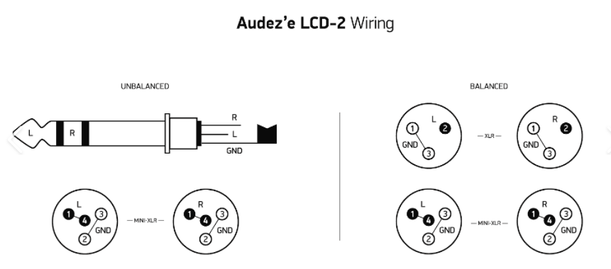
1- hardwired cable,
2- external screen removal,
3- trapazoid treatment.
What I’m doing is simply adding 20 durometer 0.75mm (1/32”) rubber sheet material in the shape of the ‘Clamp Ring’ which is ‘stuck’ to the metal side of the ring (think gasket).
I have used double sided sticky tape and also ’Sticky dots’ (a 3m product) that is applied from a dispenser and rolls onto the flat surface leaving small dots of glue behind.
I punch holes in the ‘gasket’ for the screws to pass thru to their ‘seats’.
And so the ‘Clamp Ring’ is put back in place, upside down from it’s ’stock’ position.
With the original open cell dampening material facing ‘out’ (towards our ears).
And during the re-assembly, the inside edge of the Clamp Ring should not have any of the ‘gasket’ material binding on the outside lip of the driver assembly, as the ‘Clamp Ring’ gets tightened down.
Be sure to BACK the screws out to find their originally cut threaded slots, before screwing them in.
Trust me on this.
You are going to want to tighten these screws down so that the inside edge of the metal Clamp Ring is at or below the lip of the driver assembly opening.
Do this in steps like torquing down a head on an engine rebuild, only use more steps.
This means you must be careful and not ham hand these #6 torx screws.
Not to mention it would be bad form to poke a hole in the diaphragm with your very pointy torx bits.
So use caution and don’t let the driver slip when tightening those tiny screws down.
Seat them evenly and carefully because they will be tight and it is possible that they can strip out (or break) their ‘seats’.
But if you screw up, repair parts are available from Sennheiser, but know it will take weeks perhaps even longer to get them (see the cautionary notes above).
Also, I cut back the stock open cell foam (which should now face ‘out; towards our ears) at a ≈45º angle all along the inside edge of the Clamp Ring, so as little of it intrudes into the cone area where the sound exits the driver.
Also, after several days of use I go back and check those screws to make sure they are all at set at the same torque.
And that the ‘Clamp ring’ is at a uniform height with respect to the opening of the driver itself.
You’ll probably find that the screws have settled in just a bit and a few will tighten just a touch to match the rest.
And this is important, you want all 4 screws at the same torque/equal pressure into the driver mounting structure.
And note they don’t have to be at max torque, but the ‘Clamp Ring’ should be at an even height compared to the driver opening.
So really, what have I accomplished here?
Well for one thing the ’step response’ of the driver more closely matches the input waveform.
This in and of itself should be evident as an indication of increased accuracy in re-creating our music’s waveforms, especially those oh so important Leading Edge Dynamics.
This mod reduces unwanted created acoustical energy and helps reduce how much energy spreads out in time, and so ‘contaminates’ the rest of the generated waveform.
IOW, more of the acoustic energy is created when it should be and (more importantly in this case) NOT where it shouldn’t be.
Put another way the acoustic energy created is more precisely time aligned.
This could be conceptually thought of as a form of jitter reduction in that we are increasing the precision in time and amplitude of when and how much acoustic energy is generated and then presented to our ears.
Now, 800’s are already pretty good at doing this, but this mod takes their ability one step further.
Another way of thinking about this mod is, it’s applying ‘critical dampening’ to the driver and it’s mounting structure to better control the resonant vibration of the driver assembly.
And perhaps more pointedly, is how and what the diaphragm itself is ‘anchored’ to, which establishes it’s vibrational foundation.
Is this perfect?
Of course not, but we are dealing with transducers here and we all know that they are the least precise of all of the components in our audio systems.
And as I have mentioned previously this approach could be taken to whole nuther levels, and I have no idea where that would lead to, nor how much improvement could be attained.
But I have no doubt that my results could be significantly improved upon.
But it would involve $$$$$$+ and resources not usually available to hobbyists.
So as the driver is more closely ‘dialed in’ such that it’s acoustical output more closely matches it’s input waveform, I can’t see that as anything but ‘
Better’.
And I have taken my measurements which have revealed yet further refinements, and have analyzed them at least using a back of the napkin approach and have put some numbers behind this mod.
I looked at the innerfidelity measurements of a stock set of 800’s and measured the overshoot vs the trailing edge amplitude, and did so for the Gen-6 J-mod and compared them.
The stock set of 800’s measured the overshoot at ≈ 37.5% of the total amplitude of the initial leading edge to the trailing edge.
The 800-Jmod resulted in ≈ 12% of overshoot, of the trailing edge amplitude.
By just subtracting these 2 measurements we see a reduction of 25% .
It also can be expressed as a percentage down to just 32% of the original amount of overshoot.
This is a relatively big change/lowering of what I have come to see as a Major source of listener fatigue.
This change also reduces distortion, especially the smearing of acoustic energy thru time and the addition of upper harmonics to fast rising transients (a slew rate related distortion, of sorts), that also contribute to listener fatigue.
So why would I or anyone want to do this?
To take these steps in the 1st place?
Overshoot seems like an ‘enhancement’ that is easily included in the design, one that can add that initial WOW factor (but which I call the Bose effect), one that helps ‘make the sale’ one that is ‘good for business’.
This ‘enhancement’ has auditory consequences beyond a simple WOW factor.
Stated plainly it contributes to listener fatigue and it need not be this way.
And that ugly 6.5KHz FR peak response, which has been pointed out as the source of the ‘problem’, is much less of a ‘problem’ in comparison to this listener fatigue issue.
And this added contribution to the sound signature, fortunately, can be at least in part, ameliorated.
And make no mistake the 800 isn’t the only HP that uses this ’Sales Enhancement Technique’ (SET) of overshoot.
And to be fair this SET actually helps those of us who actually like the 800.
Because they have become popular, their cost of ownership due to the used market, has lowered and so has made it easier to make mods like this more doable for those of us who tweak such things.
Ultimately though making a great HP less so (which can be reversed, at least somewhat in this case) seems like a marketing mistake, which has gone on for too long now, and of course could now be turned around into a marketing bonanza.
The sonic degradation of too much overshoot is easily heard and one key sonic attribute that suffers is Listener Fatigue, and yes there are others as well.
All in all it seems to me that if the manufacturers start to address this issue, our long sought for major acoustic improvement with all of the TotL HP’s, could be realized.
As a parting conclusion, I’d like to see the headphone manufacturers use WAY less overshoot, as in perhaps just a touch to help with the marketing side of things, the SET approach, but not enough to contribute to
tLFF, which is where we are now.
And I figure that would lead to a substantial improvement in the SQ of ALL headphones, simply because they would be more accurate in reproducing the original signal fed them.
Granted they may not be as initially spectacular, but SotA HP’s DON’T need all that sizzle, we want the steak.
JJ
End


")