The DIY'rs Cookbook

Mar 14, 2017 at 7:36 PM Post #931 of 1,974
Say there and thanks for the kudos!
 
The dimensional specs for the board only list the width and depth as 83 x 73mm.
And judging by the pictures the height is less than 73mm by ≈ 1/3rd.
So a guess is ≈ 50mm.
 
And if I remember to measure it the next time I open up the case, I'll post up that measurement.
 
JJ
 
Mar 14, 2017 at 10:37 PM Post #932 of 1,974
  Say there and thanks for the kudos!
 
The dimensional specs for the board only list the width and depth as 83 x 73mm.
And judging by the pictures the height is less than 73mm by ≈ 1/3rd.
So a guess is ≈ 50mm.
 
And if I remember to measure it the next time I open up the case, I'll post up that measurement.
 
JJ

Thanks. No rush. My D16 is only 1U thick so I do not have much height to play with. Might just stay external.
 
Mar 15, 2017 at 2:39 AM Post #933 of 1,974
Yeah 1.75" of height is a limitation for sure.
 
And 50mms of height is 1.9" which is just a touch to much height, and that doesn't take into account standoffs or other forms of insulation to elevate the board.
 
Unless a transformer and regulator board can be found with ≤1.5" heights, such as this transformer with a 30mm = 1.2" height (which won't fit in the same space as the existing SMPS, assuming it uses the same unit the RN3 uses (which is probably a safe bet).…
http://www.ebay.com/itm/4N-OFC-O-core-audio-transformer-DAC-preamp-50VA-AC18-0-18V-0-9V-0-9V-/131595356897?hash=item1ea3b1cae1
 
As for the regulator board, that might take a bit of sleuthing to find a low profile board.
 
So, I figure that for most, the D16 will be more easily modded using an external LPS, although the end result won't be as simple since there are now 2 boxes to deal with.
 
Still, this upgrade is well worth the effort and cost, at least from what I'm hearing in my system anyway.
 
JJ
 
Mar 15, 2017 at 7:34 AM Post #934 of 1,974
  Yeah 1.75" of height is a limitation for sure.
 
And 50mms of height is 1.9" which is just a touch to much height, and that doesn't take into account standoffs or other forms of insulation to elevate the board.
 
Unless a transformer and regulator board can be found with ≤1.5" heights, such as this transformer with a 30mm = 1.2" height (which won't fit in the same space as the existing SMPS, assuming it uses the same unit the RN3 uses (which is probably a safe bet).…
http://www.ebay.com/itm/4N-OFC-O-core-audio-transformer-DAC-preamp-50VA-AC18-0-18V-0-9V-0-9V-/131595356897?hash=item1ea3b1cae1
 
As for the regulator board, that might take a bit of sleuthing to find a low profile board.
 
So, I figure that for most, the D16 will be more easily modded using an external LPS, although the end result won't be as simple since there are now 2 boxes to deal with.
 
Still, this upgrade is well worth the effort and cost, at least from what I'm hearing in my system anyway.
 
JJ

 
Thanks for the added detail. I think I will try my Mutec USB first since it re-samples just before the Yggy. My HDPlex has one output that is variable so I can set it to 6.3v easily...
 
Mar 15, 2017 at 9:47 AM Post #935 of 1,974
John, my 9V Talema Transformer for the Rednet 3 is still due as the supplier on Ebay sent me 115/115 25VA -  7V by mistake. In the meantime, can I ask something?
 
I know the wiring from the JST XH connector (thanks Golfnutz). I am unsure of the output terminals on the LPS PCB. It has 4 small pads, and underneath the PCB it says 5V at pad 4 and Ground for the middle 2 or 3 pad (seen from the top as 1,2,3,4 with 4 being far right pad.
 
Can I assume pad 1 and 4 is 5V outputs and pad 2 and 3 are GRND? And we use both 5V Pads as there are 2 x 5V connections on the JST XH. I would also run the ground from JST XH out and via a chassis bolt on to the 2 x GRND pads on the LPS PCB.
 
It this correct?
 
Oddly the pic on Ebay below shows the pad 1 and 4 shorted, but my supplied LPS doesn't have that connection. Should I short it as well?


I have 2 weeks to wait now before it lands.
 
Thanks guys.
 
Mar 15, 2017 at 3:32 PM Post #936 of 1,974
The Talema I installed in the RN3 is a 115/115 15VA-7V and it is running perfect. You would have been fine with that Talema they sent you.
 
On the LT3042, you are correct that pins 1 and 4 are both +5v, 2 and 3 are both ground. You can double check this with a multimeter.
I connected pin 1 of the regulator to 1 of the +5v input on the RN3 and pin 4 of the regulator to the other +5v input of the RN3.
You can short the pin 2 and 3 of the regulator and run that to the negative input of the RN3 as I have done.
 
Mar 15, 2017 at 3:54 PM Post #937 of 1,974
Hi Muziqboy
Thanks, that is most helpful.
 
Mar 16, 2017 at 2:14 AM Post #938 of 1,974
  John, my 9V Talema Transformer for the Rednet 3 is still due as the supplier on Ebay sent me 115/115 25VA -  7V by mistake. In the meantime, can I ask something?
 
I know the wiring from the JST XH connector (thanks Golfnutz). I am unsure of the output terminals on the LPS PCB. It has 4 small pads, and underneath the PCB it says 5V at pad 4 and Ground for the middle 2 or 3 pad (seen from the top as 1,2,3,4 with 4 being far right pad.
 
Can I assume pad 1 and 4 is 5V outputs and pad 2 and 3 are GRND? And we use both 5V Pads as there are 2 x 5V connections on the JST XH. I would also run the ground from JST XH out and via a chassis bolt on to the 2 x GRND pads on the LPS PCB.
 
It this correct?
 
Oddly the pic on Ebay below shows the pad 1 and 4 shorted, but my supplied LPS doesn't have that connection. Should I short it as well?


I have 2 weeks to wait now before it lands.
 
Thanks guys.

Pins 2-3 are the 'ground' or -5Vdc connection, and pins 1-4 are the +5Vdc.
And yes I used both of the +5Vdc as well as both of the -5Vdc pins.
 
On my board the 2-3 pins were soldered together and 1-4 were not (unlike the picture above) so I used one wire (of the pair) to each of the +5Vdc pins and both of the ground wires to the jumpered grounds (pins 2-3).
 
And as Musiqboy stated the dual secondary 7Vac windings are perfectly fine for this application.
And remember that 7Vac is 7 x 1.4 = 9.8Vdc which gets regulated down to 5Vdc.
So there is plenty of headroom.
 
It will also generate less heat using the lower secondary voltage.
 
JJ
 
Mar 16, 2017 at 2:40 AM Post #939 of 1,974

Thanks JJ. Do you think the Chassis connection on the -5V feed is required still?
 
I will be doing the transplant in 2 weeks.
 
Mar 20, 2017 at 3:06 AM Post #940 of 1,974
Required, perhaps.
 
But the original design did tie the chassis and digital signal grounds together on the SMPS board, which in turn is tied into that single point chassis ground in the far right hand rear corner where the top cover grounding wire is also connected.
 
But, perhaps, and this is purely speculation on my part, the RN3 could live and operate just fine without the chassis tied into the negative 5Vdc connection at the output of the LPS.
 
When next I dive into the RN3 I'll disconnect that connection to ground and see if the noise measurements change while operating.
It might be less noisy, but then again perhaps not.
 
An interesting experiment for sure.
 
JJ
 
Mar 20, 2017 at 3:25 AM Post #941 of 1,974
  Required, perhaps.
 
But the original design did tie the chassis and digital signal grounds together on the SMPS board, which in turn is tied into that single point chassis ground in the far right hand rear corner where the top cover grounding wire is also connected.
 
But, perhaps, and this is purely speculation on my part, the RN3 could live and operate just fine without the chassis tied into the negative 5Vdc connection at the output of the LPS.
 
When next I dive into the RN3 I'll disconnect that connection to ground and see if the noise measurements change while operating.
It might be less noisy, but then again perhaps not.
 
An interesting experiment for sure.
 
JJ


I would be very interested in your findings JJ. I am not 100% sure, but think one cf the guys on here did not connect to ground.
 
Mar 20, 2017 at 4:06 AM Post #942 of 1,974
A status report on the SQ improvements due to the metallurgy mods to my system, along with the LPS mods, and the introduction of the Jggy, etc.
 
Tonight I heard the flutist inhale between measures while playing Carmen on a recording from 1979.
I never noticed that before.
 
And the SQ still hasn't peaked yet (at 1424hrs), but it is slowly and steadily moving in that direction with new nuances and mid range (and up) definition 'peeking out from around the corner', so to speak.
Like hearing the flutist breathe in between notes.
 
And I'm really close to starting to dial in my mods to the 800's.
The electronics and remaining spare parts should be showing up this week.
 
I'm jazzed to be sure.
 
JJ
 
Mar 20, 2017 at 5:15 AM Post #943 of 1,974
 
I would be very interested in your findings JJ. I am not 100% sure, but think one cf the guys on here did not connect to ground.

Yeah I vaguely remember seeing that as well.
And I still have one more set of measurements to take on the RN3 so I'll add this to the list while fussing with the innerds.
 
JJ
 
Mar 25, 2017 at 2:38 AM Post #944 of 1,974
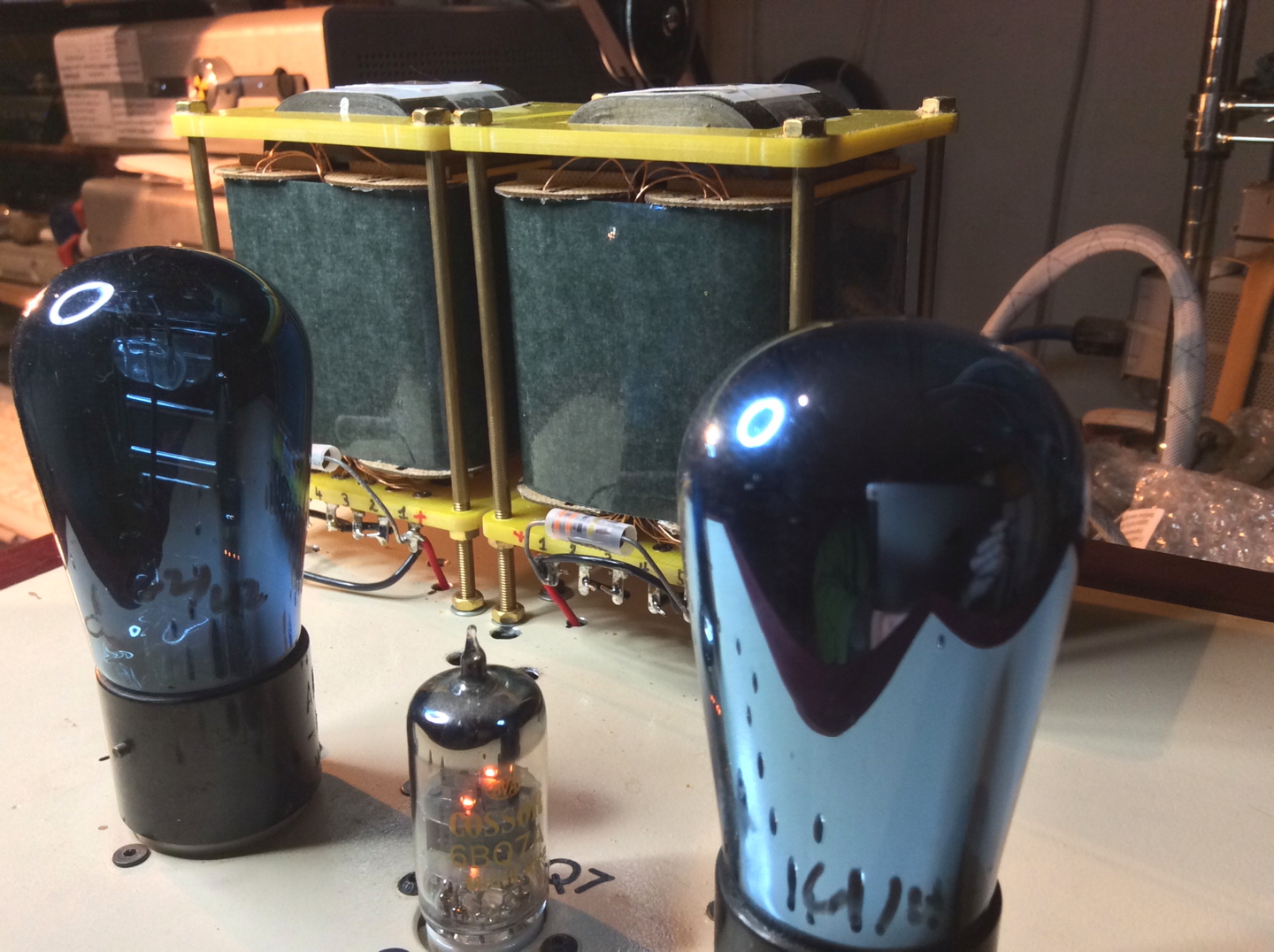
So I tore into my RN3 and added one minor mod to the lid, took some measurements and observed the LPS under a few different loads.
 
I wanted to make that top cover grounding wire a quick disconnect (spade lug) connection, for easier access to the box.
I figured it would make opening the box up, just a touch less fiddly…  :D
 

pic of RN3 grnd wire mod
 
Then I hooked up my scope and took some readings.
 
I took the 1st readings with the RN3 running normally on the new LPS.
Then I disconnected the LPS and then measured it again , then I added a small load (a 7.5KΩ resistor) and measured again.
 
But next, I’ll list the previous readings to re-establish a base line to compare all of these readings to.
And the direct comparison between the SMPS and the LPS readings, the 2 different sets of them, while operating the RN3, as in under normal load, will be where the rubber meets the road.
At least in this one example, anyway.
 
So here are the previous measurements of the RN3 being powered by the SMPS and the initial triple output LPS unit (the triple output unit).

And the noise as measured on the +5vdc is much lower than what I measured while running the SMPS.
Here are the measurements I made using the stock SMPS.
Stock SMPS
Pin #  Voltage    Average    Normal    Envelope

1           +5        11 mv    91 mv    106 mv
2           +5        83 mv    91 mv    106 mv
3     0 (grnd)    101 mv    91 mv    106 mv
Note these readings include 24µs spikes (≈42KHz).
 
And here are the readings using this LPS with a rated noise of 2mv
 
LPSx3
Pin #  Voltage    Average    Normal    Envelope
1&2
         +5          1 mv         6.5 mv        25 mv
3          0 (grnd)      3mv           16mv        27 mv (68mv with spikes)
Note these ground measurements were made using the active circuit grounds (not just the chassis grounds as were used in the measurements made with the SMPS).
Which means these measurements were made with the noise generating circuits included so these numbers are worst case instead of just the chassis ground voltages.
 
It should be noted that the envelope does include the 15.9µs (≈63KHz spikes) where as the average and normal readings don’t.
These spikes are generated by the active digital circuit itself and not by the power supply.

So now I’m gunna list these latest measurements semi a$$backwards from the sequence I took them in, that way I’ll have the conclusion at the end with a build up to get there.
 
So when I ran the LPS under no load conditions, which is the worst case to measure any PSU*, and then a very, very small load (the 7.5KΩ resistor), these reading could be considered as a base line (in situ) with the digital load only connected to the LPS by the ground connection.
Then I’ll list the Normal Operating measurements.
 
*Note SMPS’s often won’t even function under No Load conditions.
 
The periods I could capture and measure were
0.12µs = 8.3MHz
1.0µs = 1MHz
1.35µs = 740KHz
And these frequencies were present under all of these measurement conditions.
 
NO LOAD Internal LPS
+5Vdc supply Voltage with added noise as measured.
   Average         Normal                                               Envelope
    1.0mv            3.0 to 6.3mv without/with spikes       5 to 14mv without/with spikes
 
SMALL LOAD Internal LPS
LPS measurements made with a 7.5KΩ resistor
+5Vdc supply Voltage with added noise as measured.
Average                                           Normal                                         Envelope
2.6 to 4.3mv without/with spikes    2.6 to 4.3mv without/with spikes    6 to 11mv without/with spikes
 
NORMAL (Digital) LOAD Internal LPS
LPS measurements made under normal operating conditions.
+5Vdc supply Voltage with added noise as measured.
Average                                          Normal         Envelope
1.9 to 3.9mv without/with spikes    14.5mv         14.8 to 19.5mv without/with spikes

And now for the moment you’ve all been waiting for…
A comparison of the noise between the SMPS and 2 different LPS units
The results please.
 
              Average          Normal         Envelope
SMPS     83mv               91 mv           106 mv
LPS x3    1 mv               6.5 mv            25 mv    
LPS int   1.9 to 3.9mv   14.5mv          14.8 to 19.5mv   
 
What this tells me is any LPS should significantly reduce the noise on the +5Vdc rails vs. using an SMPS.
This is not really a surprise since this is well known.
But that the reduction of the magnitude of the noise should make such a noticeable change and improvement in SQ, especially while powering a fully and strictly digital device is an eyebrow raiser to me for sure.
 
And from a different perspective this is yet further confirmation of the benefits for a multi stage highly regulated power supply, especially for DAC’s and other gear that connects directly to analog gear.
Which has been a trend in current DAC designs now for a while.

Next up are the power utilization and ground noise measurements and comparison from this internal LPS vs the SMPS measurements.
 
JJ
 
ps oh and I measured the Telema transformer height .
The transformer alone is ≈ 38mm
The transformer with its mounting board is ≈ 42mm
The transformer with its mounting board on the standoffs is ≈ 48mm
 

Users who are viewing this thread

Back
Top