The DIY'rs Cookbook

Feb 14, 2017 at 7:45 PM Post #811 of 1,974
We have successful ignition of the rocket shoes (to quote Rebus Kineebus of Firesign Theater fame).
 
And thanks to Nick, MR tech at Schiit, who steered me in the correct direction, I found that I plugged the ribbon cable into only one row of pins.
 
So now the warm-up / settling in / reaching peak performance of the Jggy has begun.
 
I expect it won't take the full 7+ days, but it will be interesting to determine how long it will take.
 
Mondo headphone time engaged… 
atsmile.gif

 
JJ
 
Feb 14, 2017 at 11:21 PM Post #813 of 1,974
Congrats JJ, enjoy the experiences.

Say there SGTM…
 
At ≈ 4hrs playing time, the SQ is nearing what my PWD delivers.
 
I expect it to continue to blossom further, and if the usual sequencing holds true, by 2-4am this evening/morning I should be hearing it peak.
 
Yeah I'm having some fun now. 
atsmile.gif

 
JJ
 
Feb 15, 2017 at 5:58 AM Post #814 of 1,974
Status report.
(yeah I couldn't resist). 
atsmile.gif

 
This transition from my tweako PWD to the equally tweaked Jggy reminds me in terms of the pattern of 'behavior' that I experienced when I went from my tweaked 2-wyrd setup to the RN3 and the transition from the SMPS to the LPS in my RN3 as well.
Even if the magnitude of change is different in all 3 of these cases, the pattern and rate of changes is remarkably similar.
 
It took ≈ 1-2 hrs for the change to the 'new', to begin approaching the same level of SQ that the peak level of SQ the previous setup was capable of.
 
This slow gradual shift and change in terms of the acoustic presentation continues as the hours accumulate and at ≈10+hrs the SQ is continuing to blossom and the overall SQ has reached full parity with the previous setup.
If this progression continues, like the previously mentioned examples, then I'd expect tomorrow will be even more amazing.
 
Right now the delivery of those tantalizingly impressive inner details that tend to 'lock' the soundstage and all of the 'voices' that contribute their acoustic presence, into a cohesive whole (C3), are not just peeking from around the corner, but are 'strenghtening' in their ability to be noticed and make ever greater contributions to the overall SQ.
 
Now my ability to discriminate these subtle differences as well, is probably also being refined as I 'learn' what these differences are and what their results 'bring to the table' so to speak.
IOW I'm more fully and completely integrating these changes, and so they have more meaning.
 
Still the step up in SQ thus far is most impressive and I know it's still very early in the 'settling in' process, not to mention the 5 other tweaks I currently have running hourly counters on, that are also 'settling in' as well.
 
Interesting Times In Audio Indeed.
 
JJ
 
Feb 15, 2017 at 11:24 AM Post #815 of 1,974
I'm now an owner of my very own Jggy!
And it will be going into service tomorrow (monday) after I lightly mod it.

And I'll be selling my tweako PSA PWD mk.I-II dac here before to long


1. What're you going to do to your Yggdrasil?
2. What did you do to your PWD MkII?
- please be as detailed as you like about #2, I own one that I'm wondering about replacing or selling right now.
 
Feb 15, 2017 at 7:10 PM Post #817 of 1,974
1. What're you going to do to your Yggdrasil?
2. What did you do to your PWD MkII?
- please be as detailed as you like about #2, I own one that I'm wondering about replacing or selling right now.

Say there.
 
In the case of #2, I replaced the stock fuse with 2 'standard' (not red nor black) Synergistic Research Quantum (SRQ) fuses (it uses one for the digital and one for the analog sections of the dac).
 
I also added the WAQy (WA Quantum) fuse chips to these fuses.
And I added a WAQy transformer chip to the torroidal transformer as well.
 
Yes some might consider all of this as pixie dust or worse, but my experiments have repeatedly demonstrated that the WAQy chips do result in improvements as do the SRQ fuses.
 
I also used silver paste on the interconnects  (DO NOT use this on either the USB or the RJ-45 (ethernet) connectors) and on the fuses where they make contact with the fuse holder.
 
As for #1, I did much the same except I used 3 transformer WAQy chips (digital, analog, choke) and only one SRQ fuse along with a WAQy chip.
 
The other thing about my PWD is it started life as a Mk.1 and was upgraded to the Mk.2.
This particular configuration is reportedly THE Tweako setup for the PWD and I must say it is a delightful dac, with bass response second to none. 
The square wave response is as perfect as I have ever seen from any analog output, from any device, let alone a dac.
 
There are other tweaks but they are made to gear that plugs into these dacs and not to the dacs themselves.
 
The availability of the WAQy chips has been 'consolidated' of late, and the only place I could find them is from VH Audio.
The SRQ fuses are available from several sources and come in 3 flavors, the original SRQ, the Red version, and now the Black version, each with increasing costs.
 
Sorry I don't have any pics, although if it were important enough I could open up the PWD and show the WAQY transformer chip simply taped to the top of it. 
But the fuses are inside a covered fuse holder so there isn't anything to see that a pic would reveal.
 
JJ
 
Feb 17, 2017 at 5:59 AM Post #818 of 1,974
So today my parts came in for the internal LPS for my RN3.
It is installed and operating even as I type this.
 
Thus far it seems to be as good as my previous external LPS, and perhaps better.
 
I won't know for a while yet and I'll write up a post about the install with pics, but for now a teaser… 
atsmile.gif


JJ
 
Feb 17, 2017 at 6:51 AM Post #819 of 1,974
  So today my parts came in for the internal LPS for my RN3.
It is installed and operating even as I type this.
 
Thus far it seems to be as good as my previous external LPS, and perhaps better.
 
I won't know for a while yet and I'll write up a post about the install with pics, but for now a teaser… 
atsmile.gif


JJ

I need to lie down, this is just too exciting! I really mean it.... Look forward to your fitted and working pic (and instructions and parts list) if possible.
 
Feb 18, 2017 at 3:21 AM Post #820 of 1,974
Right now I'm in the middle of a HMMAIAA event.
 
HMMAIAA (Hearing MY Music As If Anew, Again).
 
I'm listening to the 1812 Overture, a 1962 recording using live cannons of the period, recorded at US West Point military academy.
The REALism of the cannons has taken a decided step up, including the echo reflection from the surround terrain.
 
Not to mention the carillon bells, including the sounds of the mechanism used to operate them.
 
And every album I've played today has reflected this same step up in SQ.
 
HMMAIAA indeed.
 
I'm dig'n it…
 
JJ
I still have 5 counters all counting up the hours, with the 5th (RN3-LPS) being reset to zero and starting over.
 
Feb 18, 2017 at 4:22 PM Post #821 of 1,974
  Say there SGTM…
 
At ≈ 4hrs playing time, the SQ is nearing what my PWD delivers.
 
I expect it to continue to blossom further, and if the usual sequencing holds true, by 2-4am this evening/morning I should be hearing it peak.
 
Yeah I'm having some fun now. 
atsmile.gif

 
JJ


Right on, right on!! The LPS inside the RN3 is looking good too, looks like a direct drop in with maybe some mounting rigging. Can't wait until the next meet to see/hear it all come together!
 
Feb 18, 2017 at 10:21 PM Post #822 of 1,974
Right now I'm in the middle of a HMMAIAA event.

HMMAIAA (Hearing MY Music As If Anew, Again).

I'm listening to the 1812 Overture, a 1962 recording using live cannons of the period, recorded at US West Point military academy.
The REALism of the cannons has taken a decided step up, including the echo reflection from the surround terrain.

Not to mention the carillon bells, including the sounds of the mechanism used to operate them.

And every album I've payed today has reflected this same step up in SQ.

HMMAIAA indeed.

I'm dig'n it…

JJ
I still have 5 counters all counting up the hours, with the 5th (RN3-LPS) being reset to zero and starting over.


You'll just have to learn to live with it, won't you? :rolleyes:
 
Feb 19, 2017 at 4:30 AM Post #823 of 1,974
You'll just have to learn to live with it, won't you?
rolleyes.gif

Yeah it’s a rough life but someone has to do it, right? 
atsmile.gif

 
And speaking of living with it…
 
Tonight my tLFF index reached new heights and eclipsed the old, longstanding high water mark by a relatively large amount.
 
Put another way, 3:00 was about as high as I could comfortably go with the MOAR knob before I had to turn it down.
Late this evening and onwards it hit the 4:00-4:30 mark.
 
This is a VERY encouraging sign that the degree of focus and a more precise recreation of acoustic energy is being created and presented to my ears.
IOW the energy is being expressed where it's supposed to be and not where it isn't supposed to be.
 
But that it made such a 'large' change, and so suddenly, is a 1st for me.
In the past, step ups in the tLFF were fairly small and gradual (like 0:30 increases and over the course of a day).
 
This latest shift happened in a matter of an hour or so and was very pronounced.
 
Interesting Times In Audio Indeed.
 
JJ
 
Feb 20, 2017 at 4:59 AM Post #824 of 1,974
RN3 power supply upgrade details.
 
So here is the write up of my latest science experiment and bit of Audiophoolishness…  
 
I removed the stock SMPS power supply and replaced it with a collection of parts to make up a LPS of suitable capacity and capability.
It is overkill to a certain extent but then that is a usual and expected trait for these sorts of things.
 
The power supply I added to the RN3 consists of a Telema 25VA transformer
http://www.ebay.com/itm/131363018720

mounted to a circuit board
http://www.ebay.com/itm/131863613806
 
feeding an LT3042 ‘precision’ +5Vdc regulator board
http://www.ebay.com/itm/142115498378
 
All of which feeds directly (hardwired) to those pair of wires I previously soldered to the main board.


What follows isn’t a ‘strict’ electronic analysis but is meant for clarity and ‘worst case’ figur’n, which will suffice to make the main point.
 
The transformer I used has dual 9Vac output coils and together are rated at 25VA/9V = 2.77 Amps.
And for our purposes of supplying +5Vdc to power this RN3
2.77Amps x 5Vdc = 13.88 Watts of available power.
 
The RN3 is rated to use 30 watts but I measured its current draw at ≈1amp actual power usage, which means,
1Amp x 5Vdc = 5Watts.
 
So this PSU supplies 13.88Watts and we use 5Watts, which is ≈ 36% of the rated capacity of this PSU as configured.
 
Which isn’t an ‘ideal’ percentage of this PSU, if all I cared about is % efficiency, but is perfectly fine since I have ≈ twice again the amount of current delivery capability in reserve.
 
IOW this amount of draw is sufficient to fully ‘engage’ the regulator board (so it has a sufficient load to regulate) but it, relatively speaking, is ‘loafing along’.
Which means it generates low heat, more that the SMPS to be sure but even if the entire PSU were only 50% efficient (unlikely) it would only generate ≈5Watts of heat, and it would still have almost 3 watts of reserve power remaining.
 
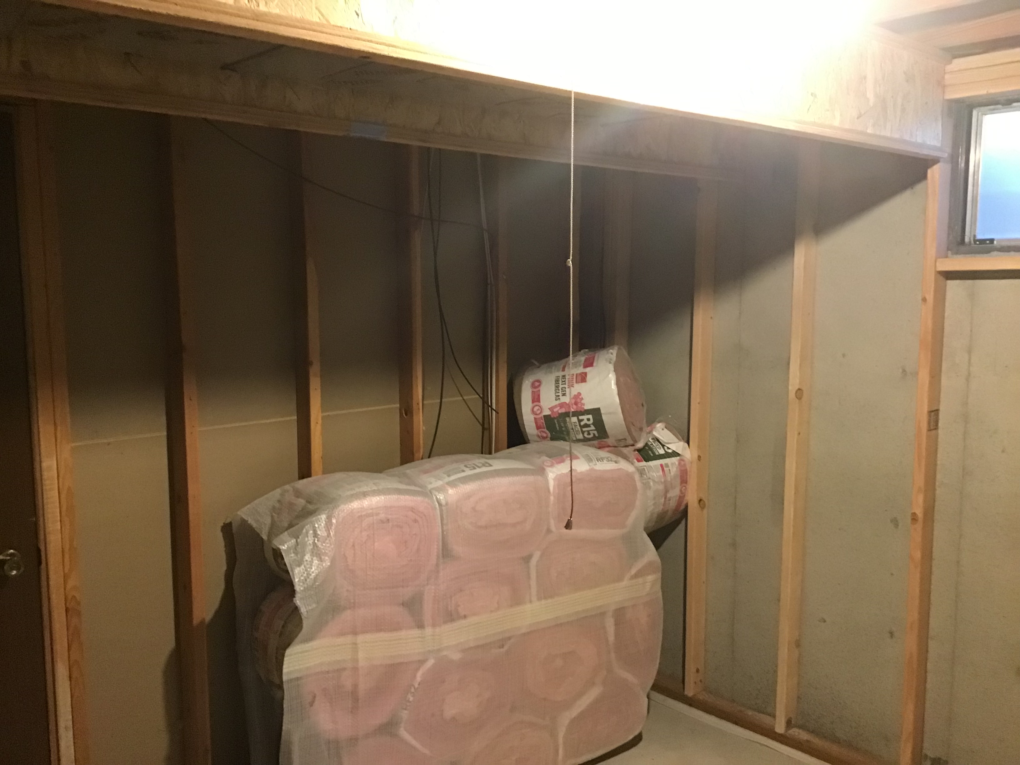
So in my original figur’n of how I’d layout this modification I was going to mount the transformer in the vacant area on the left and the regulator board near the connector block I had already added
Like this…

 
But I verified that the transformer board would fit in the space vacated by the stock SMPS.
Since I wanted to use the on/off switch and the existing IEC power connector, this arrangement would make the AC power routing much simpler, and shorter.


Be aware that the available space is a bit tight since the machine screw ’Zerk’ type fittings used to secure the sides of the top cover, protrude into the available mounting space, which in turn forces the board closer to the mainboard,
It’s fortunate that using the standoffs lifts the board above these ‘Zerk’ fittings, even so the ac power wires are positioned in this space so the extra room is a ‘good thing’.
 
And so I removed that connector block and hard wired the 2) +5Vdc wires directly to the regulator board with its 2) +5Vdc output pins, and I also hardwired the ground wire as well.


Wiring the Telema transformer board was the most tedious part in that I tried 2 different approaches with the 2nd technique being FAR easier.
 
So for those who would venture down this road I’ll save you the trouble of doing this the hard way and just explain what worked best for me.
 
The 115Vac inputs (primary windings) and 9Vac outputs (secondary windings) use 2 coils each.
They must be wired together in order to use the full output of this transformer.
Essentially the 2 coils are wired in parallel for both the input (primary windings) and output (secondary windings).
 
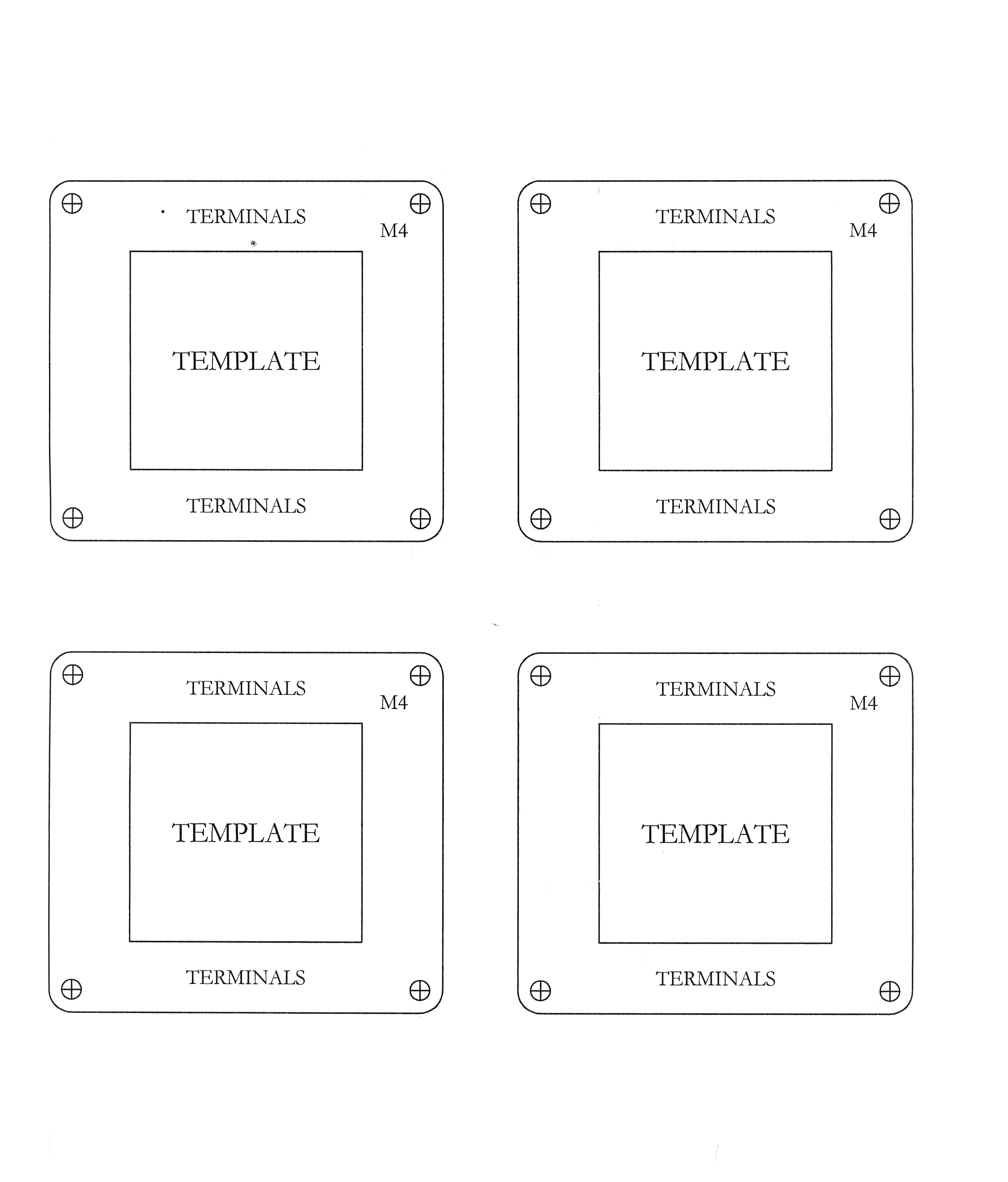
The input solder pads are a pair of ’square’ solder pads, and a pair of oval solder pads that are ’staggered’, which means the interconnection between them has to jump over one pad to get to the other mated solder pad.
They look like this,


O-X-O-X
where the O’s are wired together, as are the X’s.
What worked best was to divide the 16gauge ac power wire I used into two equal sized wires, into a ‘Y’ configuration.
These ‘Y’s then connect to both of the X’s, and to both of the O’s, where the X would be the ‘hot’ lead (Red wire) and the O would be the neutral lead (black wire) from the front panel switch.
And to possibly add just a touch of confusion, the red and black wires could be swapped between the X/O connection pairs since the load is a coil and it doesn’t ‘know’ ‘hot from neutral, nor care.
And this applies to both the primary and secondary windings.
IOW as long as both of the X’s and both of the O’s are used each by a ‘Y’ connection, the ‘polarity’ in not an issue.


I used 3 pieces of heat shrink to make the ‘Y’ so they both were insulated from each other and connected the hot on the top of the board and the neutral to the bottom.
 
I used this technique for the outputs, but the output coils are not ‘hot’/‘neutral’ but they are ‘polarized’, so the square/oval solder pads remain, which need to be wired in the same way, with the square pads (X’s) together and the oval pads (O’s) together.
 
That is if you are using 115Vac as the source voltage (like in the US).
If you need to wire the primary for 230-240Vac, the input wiring is much simpler, in that you bridge the middle X and O together and send the hot to the X and the neutral to the O at opposite ends of this connection, like this;
O-XO-X
This wires the input coils in series.  (Sorry no Picture Available).
 
I also added a 5x20mm fuse holder ($2) and wired the Brown wire (‘hot’) directly from the IEC connector thru the fuse, and then along with the Blue wire (‘neutral’) sent them on to the front panel switch, unchanged.
And I left the IEC connector’s ground wire alone.
 
The output from the on/off switch went directly to the input side of the transformer board.
And the 9Vac output from the transformer board went directly to the regulator board’s input.


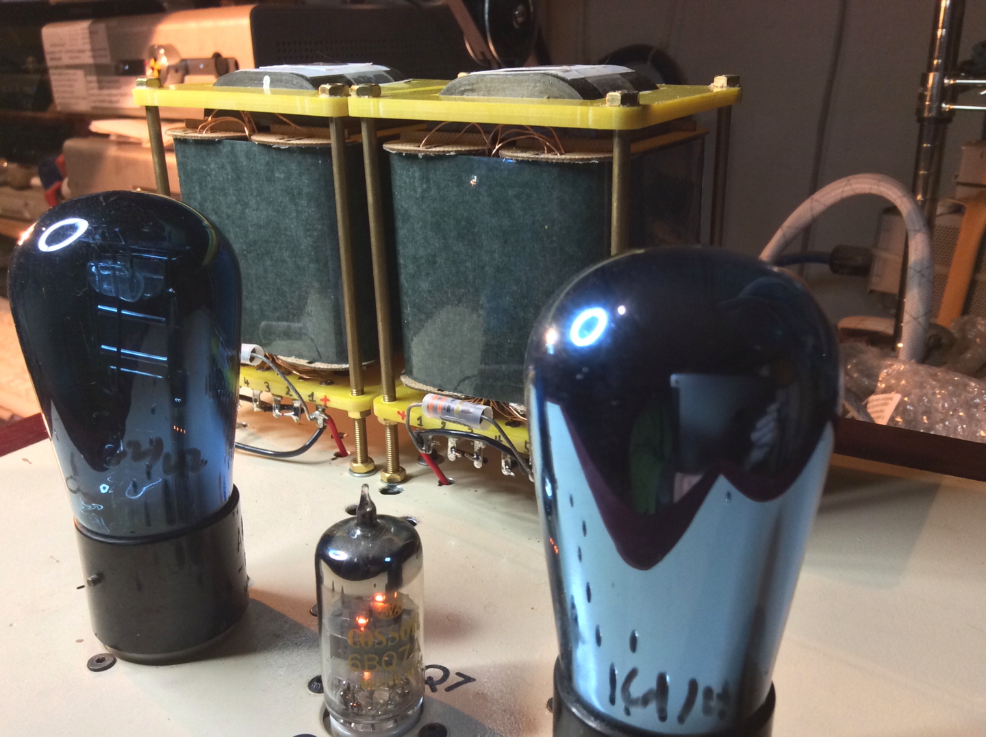
Mounting the boards was fairly straight forward in that I used 1/4” standoffs to raise the boards above the chassis.
This mounting scheme necessitated that I use nuts on the outside of the chassis which do stick down further than the tiny stick on feet, which in turn necessitated the use of more robust and ‘taller ‘ feet.


But other than the new nuts on the bottom of the chassis and the bigger feet, there is no other clue any modifications have been made to this RN3.
 
Truly a ‘sano’ upgrade.
 
And after things play for a while, settle in and I hear what the results of all of this fussing yields,
I’ll take some measurements of the power supply noise,
and the current draw in several places,
and take a few thermal readings,
and take a few more pics…
 
But in the mean time my 2 channel PSU will be built and perhaps even wired to the Mutec 3+, and I have an ac power distribution project to install as well.
 
Just WAY to much fun.  
atsmile.gif


JJ
 
Feb 20, 2017 at 1:58 PM Post #825 of 1,974
Beeeeeautiful! Sano for sure. Really like your "sleeper" approach---

"Since I wanted to use the on/off switch and the existing IEC power connector, this arrangement would make the AC power routing much simpler, and shorter..." and "...other than the new nuts on the bottom of the chassis and the bigger feet, there is no other clue any modifications have been made to this RN3."

Caring enough to retain stock functionality and appearance in a project that involves significant modifications goes way back for me. At age sixteen my first hot rod project, an Olds engine into my Ford Tudor, took almost 2 years. Other than money, a main reason it took so long was that my Dad "forced" us to do things right every time I wanted to mickeymouse something. It stuck.

Keep wrenching and soldering, JJ!
 

Users who are viewing this thread

Back
Top