More data about a LPS vs. SMPS as used in my RN3.
Most notably my RN3 just got a power supply transplant.
I changed the SMPS (Switch Mode Power Supply) for a LPS unit.
And along the way I verified that only the +5vdc is needed to operate my RN3.
I would assume (but have not verified) that the D-16 Rednet boxes operate in a similar fashion.
And after I installed my Proof of Performance (PoP) wiring and performed a few listening tests, I was wondering if the SQ shift I heard was enough to make me take the next step.
That is until I gave this setup over an hour of playing time and then went back to SMPS operation.
That is when I heard a loss of dynamic impact across the board.
So I switched back and the degree of dynamic impact just jumped out at me.
Piano, drums, guitars, violins, everything, all had a more visceral impact.
So I let it run all night and listened again in the morning and yep that increase in dynamic acoustic power everywhere was still there so I next embarked upon a more permanent install of the wiring.
In my initial PoP install I used 0.5mm (24awg) single strand wire to snag the feed into the mainboard for both the ground and +5vdc.
It was a quick and dirty install since I didn’t want to take a whole bunch of time if the results weren’t going to worth pursuing any further and I’d just yank it all out after evaluating it.

As you can see I chose a ‘local’ chassis ground for the ground because the design of the RN3 uses the SMPS as the ground source for all of the voltages it provides (+5vdc, ±15vdc and 51vdc).
And this necessitated using a different grounding scheme because the SMPS would no longer provide this ground connection.
It also should be noted that the thru holes on the main board I used to supply the +5vdc are rather small, such that even 0.75mm (21awg) wire won’t pass thru without cutting off a few strands (which is what I did).
So we are limited in the size of the wires used to supply the voltage to run the RN3.
Fortunately the current draw is under 1 amp which isn’t a problem for this gauge of wire.
And as you can see I used 2 pieces of wire which makes the wire gauge ≈21awg for both the +5 and the ground and this gauge is rated at ≈11 amps
Also you’ll notice that the grounding connection was made from the bottom of the board and the +5 was made using the thru holes from the top.
So after I figured this mod was a keeper I ‘got serious’

D) and replaced all of the single strand wire with stranded 0.75mm wire (21awg).
And again I used 2 pieces of wire for both the +5vdc and ground.

This effective dropped the wire gauge down to 18awg which has a current rating of ≈16amps.
Which in turn means there is even less voltage drop for these short wires.
And the wire gauge I used to run from the LPS to the terminal block is 16awg so the overall voltage drop should be minimal all the way around.
The ground connections to the mainboard are a bit trickier in that I had to connect them onto the existing pins that stuck out from the bottom of the board.

I split the stranded wire into to a ‘Y’ and soldered them to the short stubby pins.
And after terminating these wires with ring terminals I also used just a light touch of silver paste to further reduce the resistance across the terminal block connections, and for the local ground connection as well.

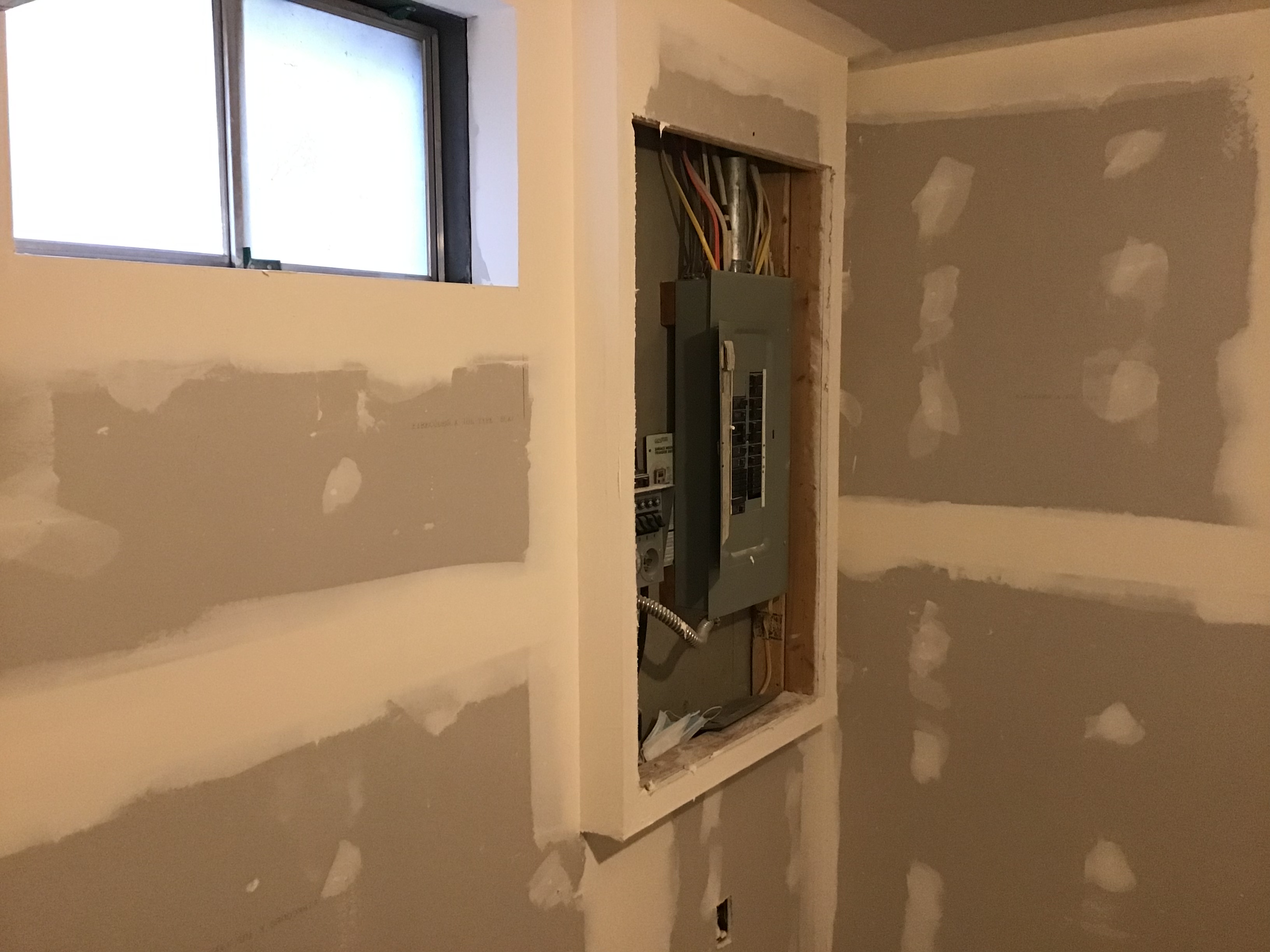
And I fed the green and white wires from the LPS thru the vent holes in the side of the top cover (which is why they are missing the red insulation, so they would fit).
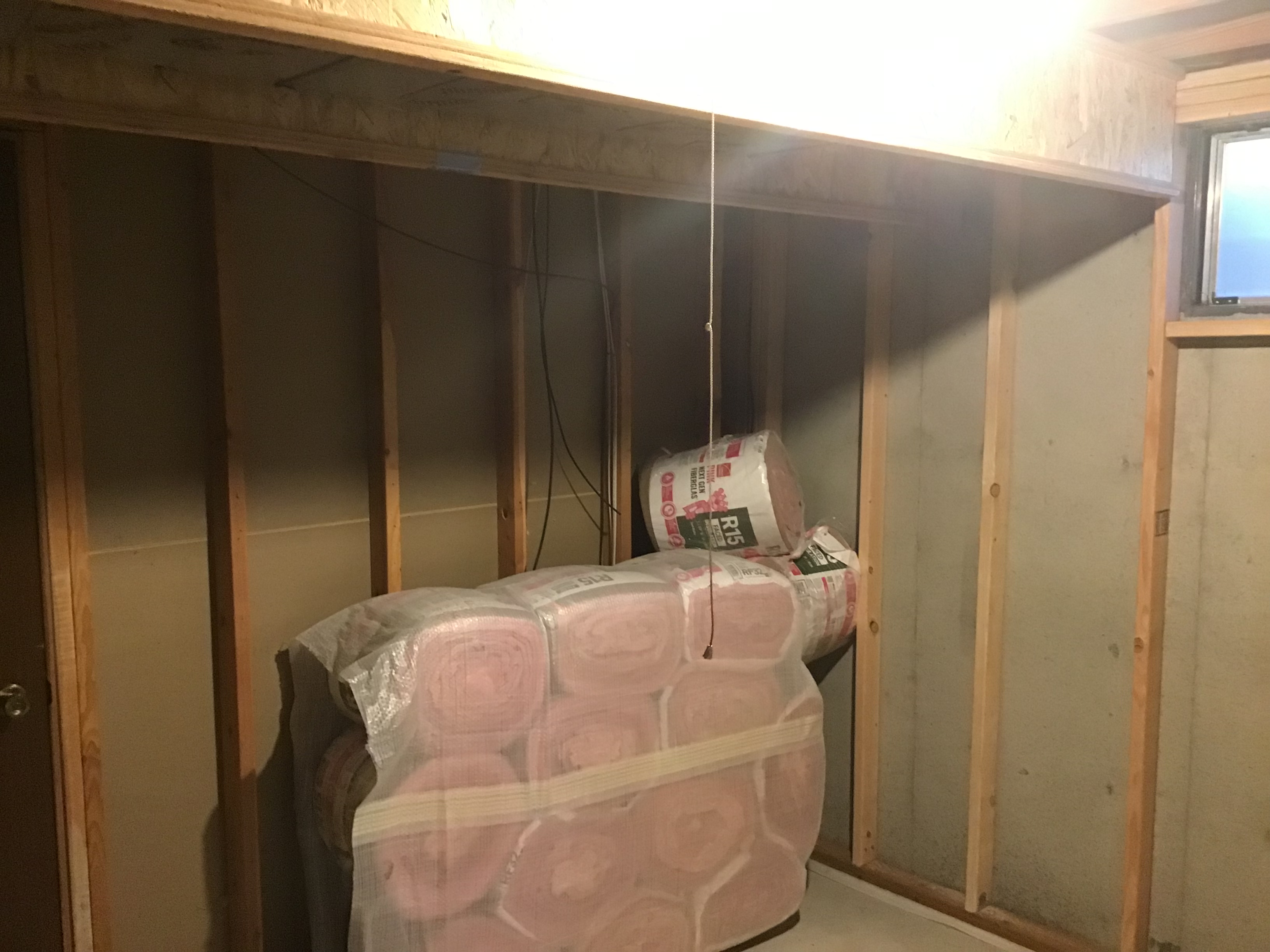
Also you can see the available area to mount a LPS circuit board in the unused area to the left.
It measures ≈ 8” left to the terminal block on the right and 3.5” deep to the main board, with a maximal height of 3.25”.
Or option #2 if I want to use all of the 7.5” depth, I’ll be limited to 3.25 width,
or a third option is about 4.5” length with a 4.5”width.
And I figure even if I need to use an external transformer, finding a suitable LPS board should be much easier.
And I did take some measurements as well.
As I mentioned the current draw is ≈ 0.9amps while running and from ≈ 0.75 to ≈ 0.85 while starting up.
So a LPS with 2-3 amps capacity would be an ideal solution.
And the noise as measured on the +5vdc is much lower than what I measured while running the SMPS.
Here are the measurements I made using the stock SMPS.
Pin # Voltage Average Normal Envelope
1 +5 11 mv 91 mv 106 mv
2 +5 83 mv 91 mv 106 mv
3 0 (grnd) 101 mv 91 mv 106 mv
Note these readings include 24µs spikes (≈42KHz).
And here are the readings using this LPS with a rated noise of 2mv
Pin # Voltage Average Normal Envelope
1&2 +5 1mv 6.5mv 25mv
3 0 (grnd) 3mv 16mv 27mv (68mv with spikes)
Note this set of measurements of the ground were made using the active circuit grounds (not just the chassis grounds as were used in the measurements made with the SMPS).
Which means these measurements were made with the noise generating circuits included, so these numbers are worst case instead of just the chassis ground voltages.
It should also be noted that the envelope does include the 15.9µs (≈63KHz spikes) where as the average and normal readings don’t.
These spikes are generated by the active digital circuit itself and not by the power supply.
But as you can see the noise on ground is ≈ cut by a factor of 4 and is reduced by an even larger amount in the average and normal measurements.
What this tells me is using an ultra low noise LPS is ‘wasted’ on this digital circuit due to the self generated noise from the digital circuit itself.
IOW the noise from the active circuit swamps out any added noise (no matter how small) from the LPS.
IOW there really isn’t any requirement to go ultra fancy on the LPS regulation, which just makes it easier to find a ‘decent’ LPS board that can fit inside the RN3.
This observation was also evident when I measured the FMC power supply voltage noise I made earlier when I compared the wall wart SMPS to the LPS I used.
IOW the noise generated by the active circuits is far greater than even a 'regular' LPS such as my 2mv rated triple PSU I'm now using.
Now it won't hurt to use a ultra low noise PSU but really you won't see nor hear any benefit just due to the lowered noise it provides.
And thus far I have found 3) LPS solutions that will fit inside the RN3 case, and can take advantage of the front panel on/off switch and use the IEC connector on the back panel, for a truly ‘sano’ install.

But as for the degree of improvement in SQ, in my system, this tweak is definitely a step up.
So much so that I’m going to pursue installing a LPS inside my RN3.
And I’ll write up a report that focuses on the SQ changes I hear in due course mostly because I’m not sure what other changes are in store as the qualitative changes that are centered around the instantaneous dynamic range and impact, continue to improve and more fully reveal themselves.
JJ