The Christiansen "DG" 300B Amplifier Build Thread

Aug 31, 2013 at 6:53 AM Post #437 of 655
I've read through this entire more monster thread, and have to say, AWESOME!

I thought I'd submit a little tip, if you don't mind? (I promise that I'm not trying to be pedantic.)

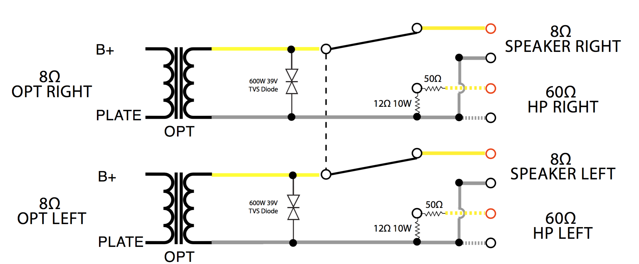
In my electronics experience, my motto is that "you can never have too much EM shielding." Okay...that comes after "always turn off the all the power supplies before fiddling," and "don't bypass the Earthing prong, even if you really really want to," and "50 kV HVDC arcing to your earthed meatbag &%£#ing hurts!" But you get the picture.

If you are paranoid about EMI giving background static and stuff, like me, you can line the inside of your nonconductive case panels with (grounded) metal mesh to make a Faraday cage. And always verify that your top and bottom panels are also grounded (just in case- cheesy pun intended :) ) If it were me making this amazing creation of yours (which I couldn't), I'd be doing that shielding, just to be absolutely sure I got the ultimate inky black backgrounds. Naturally, YMMV.

There's a reason why so much HiFi equipment is in metal casings, besides cosmetics, and why your interconnects (and your internal wiring now- bravo!) are shielded, and why some expensive units have separate PSU enclosures. (And why plastic cased laptops have those blasted aluminium sheets in them that make them so hard to repair....argh) Everything conductive, even the legs on an integrated circuit, can be an antenna.

But you knew all that already. :)

Then again, it might not make an -audible- difference given your already extensive shielding mods,but it can't hurt. It's cheap as aluminium sheets or even aluminium kitchen foil is sufficient. (Then you can use the rest of your roll to make stylin' Illuminati hats). Or aluminium metal window screen from hardware stores (that's what I use). Or you can get fancy with copper or bronze fine mesh or braiding because it looks awesome. Just make sure your new shielding is earthed :) I check my work by putting my cell phone inside, plugging the device in to earth it, and calling. It should go to right to voicemail.
 
Aug 31, 2013 at 2:04 PM Post #439 of 655
Very interesting you should bring up noise.
Why?
 
I said I'd post the good, the bad, and the ugly.  As much as I don't want to, this is an Ugly Post.
 
Out of nowhere, or maybe it's been there and slowly built up, I have developed a hum.  60Hz to be exact.  It's a bit of a moving target but it is very dominant on the left side.
 
Not kinda, sorta, might be able to ignore it.  It's there.  Right side this morning was quiet, but I know I've heard it, but much softer.  Left always.
 
What have I done to isolate it?
 
  1. Roll the glass. nothing.
  2. Turn everything off to see if it's a ground loop.  Power conditioning is from both the power entry module and a Furman 215-AC.   Nothing
  3. Purchase an Ebtech HumEx.   Nothing
  4. Yank the inputs to the driver board, thinking there might be an antenna.  Nothing
  5. I broke out the scope and made a 50Ω shunt for the HP jack.  I put a 100Hz tone and then a 30Hz tone through the inputs.  They looked fine at the HP jack and the attenuator, as expected, varied the amplitude of the sine wave.  One interesting thing.  I put the tone one one channel only.  I see the wave at normal volume on that side and nothing on the channel with no tone.  However if I crank the volume all the way up a small wave appears on the channel without a tone on the input.  (see "bleed" image.)
  6. I swapped the OPT on the Driver board.  Very interesting, the scope showed 60Hz sine wave at the HP jack…. CORRECTION pins 2 & 3
  7. I pulled both OPT inputs off the  board.  The only connection the OPT's had was to the HP XLR jack.  The scope showed a nice 60Hz sine wave on both jacks, CORRECTION pins 2 & 3.
  8. The sine wave was changing phase about once a second.   (see jumprope picture)
  9. The OPT's are mounted 2" from the Power Trans face-to-face.  I pulled the mounting bolts and moved them another inch further out.  No change.
  10. I put a small fire extinguisher between an OPT and the Power Trans.  No change.
  11. I did what your never supposed to do….  I pulled the mains ground lead from the power entry module for 15 sec.  Nothing.
  12. I'm contemplating a suggestion to terminate the grounds in a star configuration anyplace I can.
  13. Before I moved the OPT's outboard more I was certain I had a bad Power Trans.  Now I'm not so sure.
frown.gif

 
60Hz picked up on disconnected OPT's with phase shift.


Sep 1, 2013 at 5:17 PM Post #441 of 655
Question:
The scope picks up a 32Hz tone that I feed into the input when an output jack is probed. (See photo)  The setting are 10V / 10ms
With nothing connected to the inputs the scope picks up 60Hz at 200mV and 2 ms.
 
Shouldn't I have seen the 60Hz wave superimposed on the 32Hz wave?
 
Also, with the shunts in I measure
60Hz with 42mV Vrms on the left side. This is the noisier channel.
60Hz with 72mV Vrms on the right side.
 
Next I disconnect the OPT's from the driver board
I can hear hum through the HP's but not as loud.  Both sides.  In this setup I measure:
60Hz with 70mV Vrms on the left side. 
60Hz with 157mV Vrms on the right side.
 
If I clip the probe on the disconnected input leads of the OPT I measure:
 
60Hz with 95mV Vrms on the left side. 
60Hz with 140mV Vrms on the right side.
 
Since the OPT's are isolated from the circuits this tells me the Power Trans has a noise problem.  
 
Yet there are certain inconsistencies.
Such as after testing, if I pull the power plug out entirely I will still see 60Hz and 100mV Vrms on the scope.  My DMM measures about 20mV
Is this from the caps?
 
I clearly don't know what I'm doing.


Sep 1, 2013 at 7:19 PM Post #442 of 655
Do you have a high impedance probe? You should look at the noise at the tube grids, the heaters, anodes, and B+....try and track down where it's coming from. Does the output noise change amplitude when you short the input?
 
Sep 1, 2013 at 8:03 PM Post #443 of 655
I do not believe so.
I have the Rigol DS1052E
The stock probe is 10M ohm at 10X since it's measuring DC that would be the impedance with zero phase angle (As I understand it from Wikidedia)
 
Not that I'm not going to look at the grid, because that was recommended by someone else as well, But If I'm picking up 60 Hz hum, both audible and with a scope, on the outputs when the OPT is disconnected from the board entirely, it can't come from the grid or anything else on the board since it's not connected. ... Unless completely misunderstand or I'm doing something wrong.
 
The output noise does not change amplitude when the inputs are shorted.  The attenuator has no effect either.  I played music while probing at the outputs.  Turning the volume off eliminated the music wave form as expected and left the 60Hz.
 
Sep 1, 2013 at 8:26 PM Post #444 of 655
I missed the OPT disconnect part, sorry. That one puzzles me too....maybe induced?

But If I'm picking up 60 Hz hum, both audible and with a scope, on the outputs when the OPT is disconnected from the board entirely, it can't come from the grid or anything else on the board since it's not connected. ... Unless completely misunderstand or I'm doing something wrong.
 
Sep 1, 2013 at 8:31 PM Post #445 of 655
Has to be induced from the power trans.   There's no external hum.
It is so bizarre. 
The waveform amplitude is higher on the right side, but that's not nearly as loud as the left, whose wave is almost flat at the same settings.
 
It's getting worse too.
 
Sep 1, 2013 at 8:34 PM Post #446 of 655
Quote:
I missed the OPT disconnect part, sorry. That one puzzles me too....maybe induced?

I have to be doing something wrong with the scope.
 
I clip to mains ground and probe XLR Pin 2 (+).
The XLR jack has a plug with a R50 20W across Pins 3 and 2.
 
Sep 1, 2013 at 8:55 PM Post #447 of 655
Ather problem with probing the Grids or the OPT inputs is the Scope's specification for maximum input voltage is
 
[size=10.5px] 400V (DCAC Peak, 1MΩ input impedance) [/size]
 
That is exactly the voltage going into the OPT's
 
I had probed there when they are connected to the driver board and I couldn't understand why I wasn't seeing anything.  The I probed with my DMM and got 399VDC
I check the scope manual and sure enough.
 
I need the current so I can calculate the voltage diver.  I'm thinking an R1.5K should get it close to 100VDC
 
Sep 1, 2013 at 9:04 PM Post #448 of 655
Yes, that makes it hard to probe. You'll eventually find it....looks like you have a good set of test equipment.

Ather problem with probing the Grids or the OPT inputs is the Scope's specification for maximum input voltage is


[size=10.5px]400V (DC+AC Peak, 1MΩ input impedance) [/size]


That is exactly the voltage going into the OPT's

I had probed there when they are connected to the driver board and I couldn't understand why I wasn't seeing anything.  The I probed with my DMM and got 399VDC
I check the scope manual and sure enough.

I need the current so I can calculate the voltage diver.  I'm thinking an R1.5K should get it close to 100VDC
 
Sep 1, 2013 at 9:06 PM Post #449 of 655
Thanks !
I need the encouragement.
 
I'm looking at plate chokes as one thought......
But if a trans is jacked up, I want it out.  I just don't want to spend the money until I am certain it's the power trans.
 
Sep 1, 2013 at 9:26 PM Post #450 of 655
Did you disconnect the output XLR jack from ground and use a ground loop breaker for that?  I also thought you said you move the OPT out of the chassis a bit with no impact?  Try "shielding" with aluminum foil?  It's not ideal, but just to see if the noise changes.
 
Re: max voltage. There are 2 that you need to be concerned with.  One is the max of the scope itself, it says 400V, which should be using a 1x probe.  The other is the max voltage of the probe.  The 10x probe will attenuate the voltage, but it should spec a max voltage.
 

Users who are viewing this thread

Back
Top