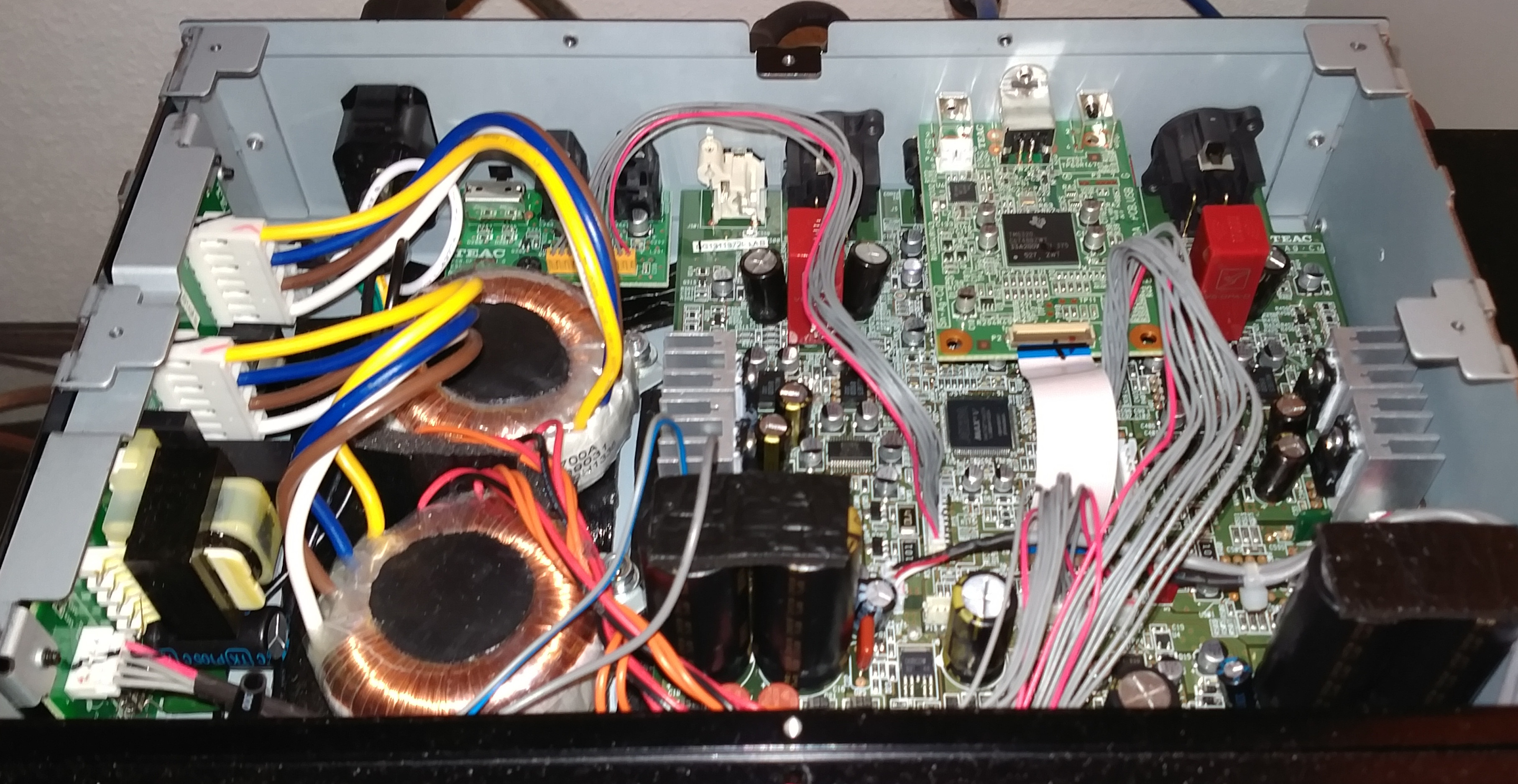
There are too many caps in the 501. Here is the photo of all of cap's groups, that I found and mark:

Could you specify the parameters of the capacitors (manufacturers, models), which you replaced the original capacitors in each of the groups?
First of all, group 1 is not a group at all. You've grouped the audio output and regulator output caps together.
The two green caps near the op amp ics at the top of the pic near the xlr in group 1 are the audio output caps. These are 100u/25V. You can replace these with Elna Silmics or whatever you like as your preference but be careful as the space is very limited in there. There are 4 of these, 2 for each channel (not in your picture).
The two green caps below the op amps in the middle of group 1 are voltage regulator output caps, and there's 2 more not in your pic (this is a dual mono design remember). These are 100u/25V. These are very sensitive to cap quality. I replaced with Elna Silmics but the sound was so dull and congested I replaced again with a tiny film cap. You can use a film cap if you replace the regulator with a Dexa voltage regulator as the designer said it is stable even with no output cap as it is so fast. Be warned the Dexa are not cheap and you'll need 4 of them. The voltage regulators are +12V and -12V, two of each. Another good regulator replacement is Sparkos.
The last bottom two in your group 1 is a regulator output cap and an headphone output cap. The brown one is the headphone out, 220u/25V. Replace with your preference.
The other one is a regulator cap but not in the signal path - it's for a relay - so you don't have to replace if you don't want to.
Group 2 is the main power supply cap. There's 4 of these, 4700u/35V. It's not easy to replace these because the diameter is so small (18mm). You can, however, squash in Nichicon KW up to 6800u/35V.
Group 3 are power supply caps for another rail, 1800u/16V. Again replace with Nichicon or other low ESR cap. A lot more space available here.
Group 4 cap is not in signal path, no replacement needed.
I also bypass these caps with a film cap. The best performance to price film cap I've found is the JB capacitor JSX series. If you solder caps to the underside PCB you can fit a 10mm diameter cap in. Just be careful of chassis screws. On the audio output caps I'm bypassing with 1u JSX's soldered beneath. They take a long time to burn in (hundreds of hours) but gives a massive soundstage, deep bass and good treble extension - makes it easy to hear differences in upsampling to 384kHz in JRiver.
I use the 501 slow filter setting which is the best, I feel. It even seems to make a difference when listening to 384k even though the filter should be off by then.
If you're good at modding, remove the cheap op amps and replace with a DIP socket so that you can roll op amps. There's 4 to do (2 for headamp and 2 for RCA/xlr). For some reason the through holes are wider than standard DIP so use an extra socket with slightly bent out pins to insert. If you're not good at desoldering, pay someone to do it.
Finally, please do modifications at your own risk. I'm not advocating any of it.