Tangent Young-Jung power supply
Jul 23, 2008 at 8:43 PM Post #33 of 162
I'd have to look more closely at those parts and the schematic but what I did was reference back to the equivalent part on the STEPS project when it seemed appropriate. Maybe that's what you're doing, but I'm at work and can't tell for sure. If not, look to STEPS for confirmation since the pre-reg stage is pretty similar IIRC.

[edit]The pre-reg stage of the YJPS is essentially the same so for C1 you want something like part # P10730 and for C2 #P10992.
 
Jul 23, 2008 at 8:52 PM Post #34 of 162
Yeah, I have looked at the requirements and it's really c2 I want confirmation on. My understanding is it is type Y and rated for 250 V AC power line. But since I haven't seen them used before in STEPS I want to confirm I'm not overlooking something.
 
Jul 24, 2008 at 2:15 AM Post #35 of 162
Yes, the line filter caps are the same in YJPS as in STEPS.

Basically, the gaps in the current YJPS docs are just in areas where I don't think there are any surprises.
 
Aug 8, 2008 at 9:59 PM Post #36 of 162
I'm getting 7.7V regulated. The only value I've change is r10 to 3.32k.
I'm getting no voltage drop across d6, so obviously that's a problem. Can't figure out why... yet.
Is there supposed to be a jumper from rsv to rsvj?
 
Aug 8, 2008 at 10:36 PM Post #37 of 162
Quote:

Originally Posted by rds /img/forum/go_quote.gif
I guess I'm missing something here, but when the r3 and r4 values in the schematic set the lm317 output to ~10V how are you supposed to get above 10v output? The build guide recommends not changing r3 and r4. I'm trying to get 30V output and my r10 and r11 values are 3.32k and 1k respectively.
As I would have expected I get about 7.7V regulated since the 317 is putting out 10v. Should I just ignore the instructions not to change r3 and r4?

EDIT it seems having about 2.5k on r4 would fix things. Does that sound right?


The LM317 floats above the regulator output voltage. As you can see in the schematic, ADJ is connected to Vout rather than ground as would normally be used. As written, the schematic keeps the LM317's output at ~2.3V above the regulated output at all times. This is the design mentioned by Jung in the 'Improved Positive/Negative Regulators' article on his site. It also appears in the National LM317 datasheet in the 'typical applications' section as a 'tracking preregulator'.

Because the prereg tracks the output, there's no need to adjust the resistors, it will always be 2.3V above the output, which gives enough headroom for the pass device to do its job.
 
Aug 8, 2008 at 11:05 PM Post #39 of 162
Quote:

Originally Posted by rds /img/forum/go_quote.gif
Thanks error401, I went back I figured this out. Now it seems the issue is that I need to jumper rsvj and rsv as well as rscg and rsrg. Sound right?


Yes. RSV and RSRG are the sense network input and ground respectively. The Jung design allows remote sensing, so if you wanted to you could connect RSV to the output at the load, and RSRG to the ground at the load. This lets the regulator compensate for lead impedance and so on. Jumpering them just connects the sense network directly at the regulator, as with most regulators you're probably familiar with.

Note: I'm going by the schematic here, I don't have one of these particular boards/designs built up.
 
Aug 9, 2008 at 12:37 AM Post #40 of 162
Quote:

Originally Posted by error401 /img/forum/go_quote.gif
Note: I'm going by the schematic here, I don't have one of these particular boards/designs built up.


Sure sounds right to me and looks to be how I've got mine configured.
 
Aug 9, 2008 at 2:00 AM Post #42 of 162
If you're worried I'll pull mine tomorrow and photograph it for you. I can't see the jumpers on the bottom so I can't confirm 100% for you.
 
Aug 9, 2008 at 6:58 AM Post #43 of 162
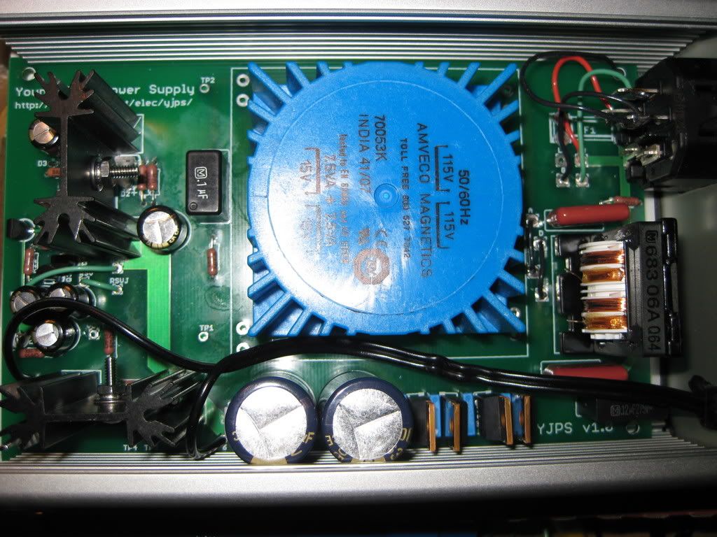
Thanks Nate - everything seems good.
IMG_0076.jpg

But if you do confirm that your jumpers are the same I'd appreciate it.
Also, another wish list board change is making Vout a larger diameter.
 
Aug 10, 2008 at 12:10 AM Post #44 of 162
I found your previous collection of articles on the super regulator and notes quite interesting tangent. How does it compare with high end lab supplies etc for its noise?

*is it at the point where to further reduce supply noise would be running up against physical limits such as Johnson noise?
 
Aug 10, 2008 at 3:52 AM Post #45 of 162
If we believe my 0.007 mV measurement, that's about 22 nV/rt.Hz over the measurement bandwidth of an LNMP. That's about equivalent to a 30K resistor. Pretty decent, considering how many parts are in the regulator.
 

Users who are viewing this thread

Back
Top