Switch box ...
Apr 9, 2008 at 11:19 PM Post #16 of 58
Quote:

Originally Posted by dgbiker1 /img/forum/go_quote.gif
You could get something like this too: Amazon.com: VIDEO/AUDIO SWITCH BOX - 4-IN-2 OUTPUT: Home Improvement

The only thing I'm wondering is if you're okay with moving your headphones between amps? You could also switch that too
biggrin.gif


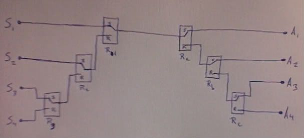
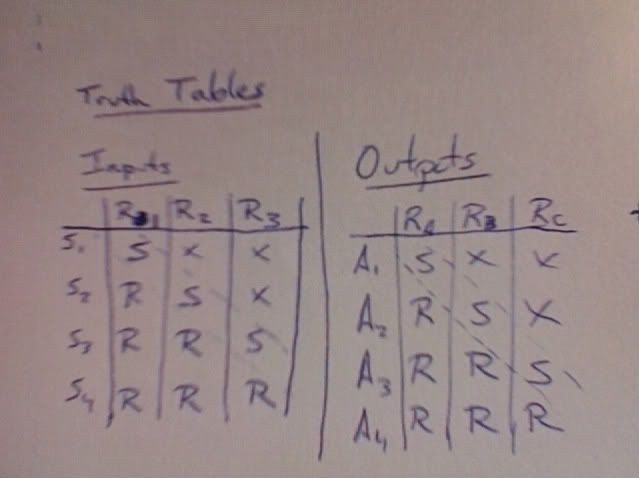
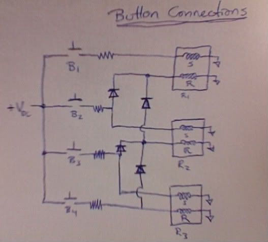
But you can still use switches and relays to achieve what you want. I have a circuit layout at home that consists only of relays and buttons that I could post if you want. In my case it fed three speakers from one amp, but adding multiple inputs should be easy if I think about it a little bit. The nice thing about the design is it was a modular branch so I can easily add a relay to the end of my circuit to add another output/input.


I'd appreciate it if you posted the circuit. From what I've read, this is an ideal first DIY project.
 
Apr 10, 2008 at 12:18 AM Post #18 of 58
Quote:

Originally Posted by scompton /img/forum/go_quote.gif
I'd appreciate it if you posted the circuit. From what I've read, this is an ideal first DIY project.


Here is my design. In my case the relays made sense because I was reading from RFID sensors, feeding the information to a microprocessor, then switching the relays (ie you walk into a room and the music gets routed to the speakers in that room). I've just sketched out how to replace the microprocessor with buttons, but I haven't calculated the resistor values one would need to use.

Here is a layout of the signal path. You can see how inputs/outputs are cascaded and could be easily scaled to however many I/Os you need. Note that this picture only shows one channel. The relays I use (Omron) are dual-pole, so you can route both channels with one relay. S1, S2... are sources/inputs and A1, A2... are the amps/outputs.
Photo19.jpg


To control the relay switching you have to excite the set or reset coils (Omron's terminology, not sure if this is standard). Note that the above picture had an "s" for the set condition and "r" for reset. The truth table for the design is:
Photo21.jpg

Where S is set, R is reset, and X is doesn't matter
smily_headphones1.gif
Note how the table forms a diagonal of S's, so the more relays you add the longer the diagonal gets.

The button layout to implement the truth table is:
Photo20.jpg

This part of the circuit is completely conceptual at the moment. In my application I had a microcontroller exciting the coils so I didn't have to worry about the diodes. I've added diodes in a few places because it looks like pressing B4 would simultaneously set and reset R3 (tearing a hole in the universe). I stuck in the diodes to prevent the signal from finding it's way back to the set coils. I haven't calculated the Resistor values since they will depend on your supply voltage, coil resistances, and diode properties. Again, note that you can just follow the same pattern as you add relays/buttons.

Here's a diagram of the Omron signal relays I use. You can see the coils where the buttons connect to on the left two terminals, and the signal path on the right three terminals.
Picture1-1.jpg


Clearly the rotary switches are more straightforward
biggrin.gif
This was just the first layout that came to mind when I saw the topic since it's what I used. In my case I couldn't use a rotary switch since the user was in a different room and making the processor physically turn a switch would be awkward.
 
Apr 10, 2008 at 6:44 AM Post #20 of 58
Quote:

Originally Posted by pinkfloyd4ever /img/forum/go_quote.gif
surprised no one else has mentioned it yet... Darwin - Natural Selection


Yes, I've used these in my preamp.

Using multiple boards, you can build them up with just as many inputs/outputs as you need.

You do need to find a 5v supply, though.
smily_headphones1.gif
 
Apr 10, 2008 at 7:57 AM Post #21 of 58
Quote:

Originally Posted by scompton /img/forum/go_quote.gif
I've looked for similar thing for a while. I saw a overkill kit and book marked it, but I've lost all of my bookmarks somehow. Anyway, a quick search of the Post pics of your builds thread

http://www.head-fi.org/forums/f6/pos...ml#post2008159

http://www.head-fi.org/forums/f6/pos...ml#post3535067


yeh thats the kind of thing im after doing. I guess that uses a rotary switch in the design connected to a load of rca's. Is it that simple?
 
Apr 10, 2008 at 8:10 AM Post #22 of 58
Quote:

Originally Posted by akione /img/forum/go_quote.gif
Yes, I've used these in my preamp.

Using multiple boards, you can build them up with just as many inputs/outputs as you need.

You do need to find a 5v supply, though.
smily_headphones1.gif


was it fairly easy to put together? I might just aswell buy this kit. I take it a 5v supply is easy enough to find? Where did you get yours?
 
Apr 10, 2008 at 10:16 AM Post #24 of 58
Quote:

Originally Posted by fault151 /img/forum/go_quote.gif
Can the Darwin design be reversed in the way it works? It has 6source inputs to 2 outputs, i need 6 outputs with 2/3 inputs.


Yep, no problem. The boards have 6 channels linked and 2 channels. You can make each group whatever you want.
smily_headphones1.gif

In your case just use it reversed, 2 in, 6 out.

The boards are easy enough to build, but I would advise that you make sure of what you want from the start.
It's not easy to remove the relays and connectors, if you change your mind ... like I did
wink.gif

The worst part is the Molex connectors
smily_headphones1.gif


I made my 5v supply from a 7805 regulator, a few diodes and caps, and, of course, a transformer. Pretty standard fare .....
If you're only running that, you'll only need a supply of ~50mA, as there'll only be 2 relays open at a time.
 
Apr 10, 2008 at 10:22 AM Post #25 of 58
So i would build it as they have designed it, but just swap my rca's over when i plug them in? EG, plug my 2 sources in and my 6 out out amps in.

Do you have the layout of the power suply you made, I wouldn't know how to make it from scratch. Im not very advanced in diy.

Cheers.
wink.gif


Quote:

Originally Posted by akione /img/forum/go_quote.gif
Yep, no problem. The boards have 6 channels linked and 2 channels. You can make each group whatever you want.
smily_headphones1.gif

In your case just use it reversed, 2 in, 6 out.

The boards are easy enough to build, but I would advise that you make sure of what you want from the start.
It's not easy to remove the relays and connectors, if you change your mind ... like I did
wink.gif

The worst part is the Molex connectors
smily_headphones1.gif


I made my 5v supply from a 7805 regulator, a few diodes and caps, and, of course, a transformer. Pretty standard fare .....
If you're only running that, you'll only need a supply of ~50mA, as there'll only be 2 relays open at a time.


Apr 10, 2008 at 10:29 AM Post #26 of 58
Hi fault151,

I've just realised you're very much a noob at DIY.
smily_headphones1.gif


I don't think you'd have any problem building the Darwin, itself, but it is a little fiddly.

The 5V supply is more difficult for you. As a temp solution, it could be powered from batteries,
or if you can find a small, regulated wall wart of maybe 3.5V nominal, that should be OK.
I've used such a wall wart for 6V relays in the past, so it should be OK for 5V ones,
as long as it's below about 7.5V.
 
Apr 10, 2008 at 10:36 AM Post #27 of 58
LOL, posts crossed ....
smily_headphones1.gif


Yes, you have it about right.
smily_headphones1.gif


I think my other reply answers your other question. You don't need an elaborate supply for this.

If you really want to make one, have a look at the Data sheet for the 7805 regulators, as they're very easy to use.
Mine was fed from an a.c. supply so I had to include a rectifier stage and a smoothing capacitor, otherwise it's as per data sheet.
 
Apr 10, 2008 at 10:55 AM Post #28 of 58
Quote:

Originally Posted by akione /img/forum/go_quote.gif
LOL, posts crossed ....
smily_headphones1.gif


Yes, you have it about right.
smily_headphones1.gif


I think my other reply answers your other question. You don't need an elaborate supply for this.

If you really want to make one, have a look at the Data sheet for the 7805 regulators, as they're very easy to use.
Mine was fed from an a.c. supply so I had to include a rectifier stage and a smoothing capacitor, otherwise it's as per data sheet.


yeh i am new to diy. I dont think id have any problems putting it together, as long as i had some sort of diagram to refer to. I think i'll order one and then worry about the power supply after. I'll take a look at the data sheet.
 
Apr 10, 2008 at 11:15 AM Post #29 of 58
am i right in thinking the relay method for a switch box is better than controlling the siwtching just via a switch control like Bjornboy81 build.


http://www.head-fi.org/forums/f6/pos...ml#post3535067

Is this beacause all the audio signal will be controlled via the relays and not through the switch?

Bjornboy81's version doesn't need a power supply.
 
Apr 10, 2008 at 12:03 PM Post #30 of 58
Quote:

Originally Posted by fault151 /img/forum/go_quote.gif
am i right in thinking the relay method for a switch box is better than controlling the siwtching just via a switch control like Bjornboy81 build.


http://www.head-fi.org/forums/f6/pos...ml#post3535067

Is this beacause all the audio signal will be controlled via the relays and not through the switch?

Bjornboy81's version doesn't need a power supply.


Yes, that's about it. The relays are much better for signal switching, than the switch contacts.
It's also easier to get the relay board close to the sockets, without having to use extension linkages, etc.
If the switch is in a separate case, it's probably not as serious as if you have other electronics in the same case.

Whether you could hear the difference .............
rolleyes.gif


I like to use relays just because I can
wink.gif
biggrin.gif
 

Users who are viewing this thread

Back
Top