Supra Schematic?
Jul 24, 2009 at 7:12 PM Thread Starter Post #1 of 16

Tyson

Headphoneus Supremus
Joined
Apr 17, 2003
Posts
2,165
Likes
32
Hi all,
Does anyone have a shematic for the Singlepower Supra SE (single ended) amp? I've been asking Mikhail for one, but no response. I have a friend that is a good tube tech and I want to have him give the amp a check up for me.

Thanks in advance for any help.
 
Jul 24, 2009 at 8:42 PM Post #2 of 16
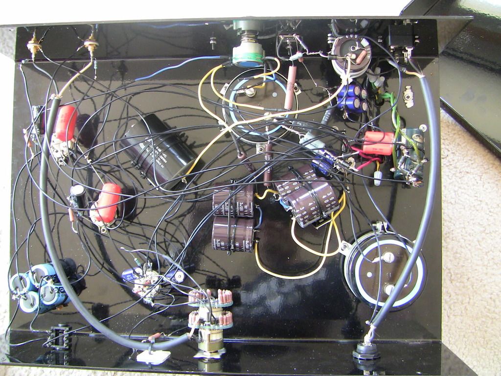
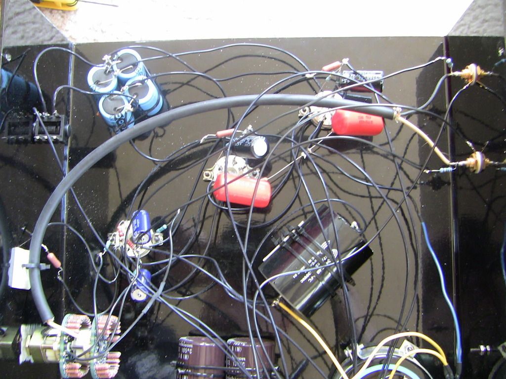
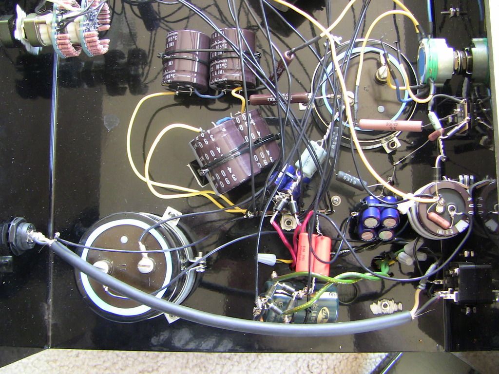
I understand that pictures of the internals might help identify which version this is. Here they are. Looking at it, it seems as though the wiring, parts quality, and implementation are pretty solid. This is one of the first ever Supras built:

IMG_0196.jpg


IMG_0194.jpg


IMG_0197.jpg


IMG_0198.jpg


IMG_0199.jpg
 
Jul 24, 2009 at 10:23 PM Post #3 of 16
Wow. Typical mikhail, and years ago he promised he would never ever
put the 2 monster caps in series without leveling resistors. Have schematic now.
Need to put numbers on things. Need values for green filament cap, light blue
resistors (4 in parallel) Actual values of monster caps, blue caps (4 in parallel)
Values of the orange drops... Black resistors (2 in series) ...

drawn by me from pictures above. Pretty close, need to fill in values.
No attempt to obfuscate the design, so no violation of DMCA.

http://gilmore.chem.northwestern.edu...oursuprase.jpg
 
Jul 25, 2009 at 8:28 PM Post #4 of 16
leveling resistors?
 
Jul 25, 2009 at 8:47 PM Post #5 of 16
100k resistors across each of the series connected capacitors.
 
Jul 25, 2009 at 9:02 PM Post #6 of 16
If you find all the values needed, would it be a good project to DIY ? (with the right parts of course, I heard mikhail used to low voltage for caps and diode bridge).
Just took a look at the schematic, why would he put the capacitors in series ?
 
Jul 25, 2009 at 10:24 PM Post #7 of 16
Quote:

Originally Posted by Tyson /img/forum/go_quote.gif
I understand that pictures of the internals might help identify which version this is. Here they are. Looking at it, it seems as though the wiring, parts quality, and implementation are pretty solid. This is one of the first ever Supras built:


I'm not sure if you're serious when you say that it looks solid?

Lots of components not properly secured to the chassis, wiring is a mess, and so on. I can't comment of the schematic, we have Dr. Gilmore for that!
smily_headphones1.gif


But from the little I know that isn't a gret work...
 
Jul 26, 2009 at 12:27 AM Post #8 of 16
updated schematic with almost all values.
Same place and name.

All i'm going to say is that this and many of mikhail's other designs
are certainly unique in both design and manufacture.

Moar voltage does not solve the problem of the inability of a WCF to
drive large voltage swings into low impedance loads.

Stuffing the output tubes with 6BL7GTA's when the plate resistor is 200
ohms does very little good. Given the headphones desired it would
be much easier to convert the thing to SRPP and run the tubes at
10 watts each.

Better would be to gut the entire thing and turn it into an extreme. Which
would require changing every single part including the transformer. And then
you end up with a beefed up version of my personal extreme with the power
transformer replaced with a custom electraprint.
http://gilmore.chem.northwestern.edu/kgextreme1.jpg
http://gilmore.chem.northwestern.edu/kgextreme3.jpg
http://gilmore.chem.northwestern.edu...rextremekg.jpg
 
Jul 26, 2009 at 6:35 PM Post #10 of 16
Quote:

Originally Posted by kevin gilmore /img/forum/go_quote.gif
updated schematic with almost all values.
Same place and name.


If its any help, the values in the current schematic MOSTLY line up with what my supra was, with the exception that the cathode resistor in the output stage in my amp was 200-ohms. minor details.

My amp had adjustable bias which was a 3-pole switch which was set to "open" 2.2kohm and 4.4k ohm in parallel with the 200 ohm cathode resistor to give effectively 200, 198, 196 ohm cathode resistors. I always thought of replacing the cathode resistor with 220 ohms (which the MPX3 uses) and using a 4-pole switch to get 220, 210, 200, 196 ohms, but cest-la-vis.

The "HV" switch on my amp was also configured differently.

Your tech should be good to go and modify the schematic on the fly with what KG posted.

From the photo posted above its probably something like a resistor or cap that broke free due to air-wiring a heavy part (facepalm)
Quote:

Stuffing the output tubes with 6BL7GTA's when the plate resistor is 200
ohms does very little good. Given the headphones desired it would
be much easier to convert the thing to SRPP and run the tubes at
10 watts each.


but with SRPP you have the problem of designing the circuit for a specific load impedance which WCF is not sensitive to. A WCF has its problems, but they are not as extensive as a SRPP into an "unoptimized" load.
Quote:

Better would be to gut the entire thing and turn it into an extreme. Which
would require changing every single part including the transformer.


voltage regulator tubes acting like audio tubes VS small-signal audio tubes acting like power tubes. 6 of 1 half a dozen of the other.
 
Jul 26, 2009 at 9:33 PM Post #11 of 16
There are no GOOD answers. Just a lot of less BAD ones.
The headphones tyson wants to use are 25 ohms. You can
with 6bl7's optimize a SRPP for that. And only that. You can
gut the thing and change it. Or you can throw it away and
get the headphones rewired and get a mid side atmasphere.
Compared to what was spent, and what will be spent in the
future, the last option seems way better if you really like that
particular sound. And you can always use it to drive speakers
when not in the headphone mood.

by the way, what happens to a transformer completely missused for the purpose.
http://gilmore.chem.northwestern.edu...hourtranny.jpg

Quote:

voltage regulator tubes acting like audio tubes VS small-signal audio tubes acting like power tubes. 6 of 1 half a dozen of the other.


Not really the same thing. The idea is to get as low a Rp as possible. There are very few tubes that
can do that. The 6c33 is the best at that. Even tubes with an Rp of 2k really aren't sufficient.
 
Jul 29, 2009 at 3:12 AM Post #13 of 16
Quote:

Originally Posted by Bolder /img/forum/go_quote.gif
Hmmm. Looks rather close to this classic Optimized Morgan-Jones circuit

cmoy5_1a.gif


Nice find for a first post! Yep, except some values and the pot arrangement this is quite the same design. Can't access HW library, how old is this Morgan Jones design?
 
Jul 29, 2009 at 6:29 AM Post #15 of 16
Quote:

Originally Posted by Bolder /img/forum/go_quote.gif
Hmmm. Looks rather close to this classic Optimized Morgan-Jones circuit


Nothing except the basic topology is the same.

Its much closer to the 6n1p amplifier one line down on the project pages but with the addition of an active voltage regulator.

The supra PS is funky, but everyone wanted more voltage more voltage more voltage and never really looked at what it did they just wanted more voltage because more voltage is moar betterer. The key to building an amp like this better is not more voltage but more current. The weakest variants of this kind of amp can drive any known 300 ohm headphone loud enough to overcome the noise at an NYC meet
wink.gif
voltage output is not an issue with a WCF unless you are especially daft. The issue is the current and how the amp deals with low-impedances. A 6sn7 at the sane limit of its current (say 14mA/135V rather than 10mA/160V which is what the SP supra ran... the MPX3 was about 8mA/160V {per section in the output stage}. in HV mode, the bottom tube which sets the current "sees" the same voltage and sets the same current but the top tube has about 100 extra volts to deal with and the corresponding currents 6sn7 is fuxored for plate dissipation so you get the fun of 6bl7/6bx7), but very conservative voltages would be pimp in a WCF, but we all formed a line demanding more voltage. In the end Mikhail as a designer holds infinitely more blame for caving to these demands than non-techies are for making them. He cranked the voltages up so high so that an amplifier which could have been made (was made) well with 6sn7 had a mode of operation that would only run properly with big power type tubes.

Nobody ever sought a high mu/low Ra/high current tube for this type of amp which would have rocked it for output impedance. 5687 with mu of 20 has good Ra, and good current capacity, but 20 isnt exactly high mu... try something with mu in the 40 ish range. maybe a triode strapped small signal pentode
smily_headphones1.gif


At that point, we must ask, is this design REALLY worse than the alternatives in an OTL all-tube audio stage using small tubes of the types commonly used in audio preamps? SRPP? the sad joke of a class-AB played on those who are not careful enough to use it with an appropriate load - this joke is played on this forum daily so how could anyone point a finger at mikhail for using a circuit that will never run outside of class-A (IE a WCF CAN NOT run class-AB) in any acceptable fashion. Pure cathode followers? an option with big tubes, but then we get into all of that....

Eventually the more voltage line grew kind of thin because you can only go so high before things start to blow up even if you were already exceeding part ratings by a little bit, and looking at it backwards it really was a very weak idea from day 1. Somewhere in there the desire for a very high current amp came up for people who need more than the 16mA (peek to peek ) output current an MPX3 can dish out at a reasonable price. Behold! The Extreme. nobody said hey can we get more voltage? This time they said more current! Perhaps too far the other way considering the great lengths mikhail went to to **** himself with this amp. Some of it could be written off as ignoring the necessity of a safety factor on some parts, others are just dum. But we got an amp that could dish out well into the 100mA output current range. Because we need 100mA of output current (yea, sarcasm) to drive headphones.

Every design topology has its compromises. Mikhail's problem wasn't one of using inherently poor topologies, clearly I and many others who have heard his amps without knowing about some of the monsters that live in these little cases would argue that his chosen topologies are nicer than some other designs that only have military grade circuit boards (whatever that means) going for them, his problem was his supreme ability to take what was a nice design and screw it up.

Someone above asked if an MPX3 would be a nice amp to clone:
Yes. If you are comfy building a HV amp like that, do it! spend a few hours with a calculator and sort out some of the screwups in the supra PS or just use the MPX3 PS... The casual observer will note that it has 2 RC filter cells before the active filter where the supra only has 1. more filtration IS moar better.

here is what the SP MPX3 toaster had if someone would be kind enough to draw a schematic:
600vct transformer
full wave rectifier, CT grounded
similar 4*10uf cap arrangement to the supra
300 ohm 12W
big blue cap. 450uf/450v?
300 ohm 12W
big blue cap. 450uf/450V?
similar voltage regulator to the supra, with the exception that B+ on the "amp side" of the reg is 350V.
I did not note the sizes of the "big blue" caps on my schematics so your on your own... If someone with a toasterstyle MPX3 could verify {or not} my values I think the community would benefit from it. as a bonus it dosnt even require opening the amp, just reading off the values.

ooh, one last note, I think B+ on my supra was 350V, but maybe my memory is foggy. I like 300V better anyways, and have seen references to 320 elsewhere on these forums. Most likely like many things singlepower this simply varied from unit to unit so don't be surprised if you find that while trying to diagnose a screwed up amp.
 

Users who are viewing this thread

Back
Top