


So beefing up the power supply makes sense to me. But I'm a little confused here as to your variation-twist to the Spritzer mod. Come again as to why the additional resistors are needed? Can you post a photo of what this looks like?
You are using an out of date browser. It may not display this or other websites correctly.
You should upgrade or use an alternative browser.
You should upgrade or use an alternative browser.
stax srm717/srm727-11
- Thread starter duncan1
- Start date
-
- Tags
- stax-srm-717
drp
500+ Head-Fier
- Joined
- Oct 24, 2003
- Posts
- 699
- Likes
- 11
duncan1,
Thanks for posting your modifications and thoughts on the 727ii. Those of us with the 727ii, and others looking for a mid-cost electrostatic solution, really appreciate the time and effort you put into typing out your findings, however they may be formatted.
I made my way through the entire thread with even greater interest because I performed Kevin and Spritzer's negative feedback loop mod a few months ago; have been curious as to what level of power supply mods could be performed. RE: The experts in this community (Kevin and Spritzer) pointed out the PSU as another weak link in an otherwise good+ stat amp (once modded).
In your first post, you wrote "If anybody is interested I will continue." The fact that the typed English language is obviously quite low on your list of priorities, and you've only gotten a few very gentle nudges to use the Enter key, should speak volumes as to the very high level of interest we have in your thoughts and modifications (other topics would have been less accepted for the given writing style). Please continue sharing, even in your own way.
You also wrote (I think) that you want others to be able to perform your mods and get our 2K amp to a much much higher level of performance. With regard to actually making it possible for the layman that's handy with a soldering iron and volt meter (like me) to actually perform these modifications, an easier to follow procedure would be needed.
If you would be interested in writing up your full modifications, by section and with part values, etc., and then PMing them to me, I would be happy to work with you to translate this information into a step-by-step procedure. The most important aspect would be defining the relative level of knowledge/experience needed, as we are talking about a device with very high voltages.
Thanks for sharing, and welcome to the community.
duncan1
500+ Head-Fier
- Joined
- Mar 3, 2012
- Posts
- 724
- Likes
- 33
NUMBER9= Spritzer connected a 150KOHM resistor to the beginning of the chain of two resisters in series coming from the new output on the channel cards back.two were used because of the low voltage of each PCD resistors to make up the voltage .I have found out you only need =one=500KOHM-upwards[to suite yourself] on listening ] if you use 250V working ones.There are several things that must be taken into account=1=Connecting Two feed-back resistors to each other is no t right =it means BOTH go down the same path.You will think=smoother. but on listening the detail is recessed.not right.so it must be fitted at the TOP end of those two feed-back resisrtors. This gives a very clear and detailed output=BUT=doing thid this before doing the other mods will just make it sound maybe even worse as you are opening it out without doing anything else=2=ANY change to the feed-back produces a proportional change to the VOLTAGE output =did Spritzer not tell you to check the balance of the two sides on each card??=and because of being DC connected there is INTERACTION between the two adjustment presets on each card meaning you will have to adjust the voltage as well[ usually upward as feedback lowers output.Wiy without doing that you will find the voltages very unbalanced.You can do it but dont expect miracles without doing ant any other mod.
duncan1
500+ Head-Fier
- Joined
- Mar 3, 2012
- Posts
- 724
- Likes
- 33
DRP =Thanks for your nice post .Your right I am what you would call in the UK a bit ex centric=BUT this in no way imp ares my intelligence or " down to earth approach.You are right about the high voltages while my health has never been good . I am Lucky enough to be born with a high body resistance to voltages due to thick skin otherwise I would be dead long ago and yes I have had several shocks from the HV-power supply -very sore others with thin /moist skin would be wise to make sure that the voltages in the capacitors is drained before starting.But if you take a chance -use ONE hand only put the other behind your back [so the HV doesnt run through your heart] to earth. The level of knowledge required is Medium-ie used to working with the basics of electronic circuits AND can recognise resistors/capacitors Buy a good so;soldering iron -better still a quality Soldering station=it will last years longer than any single soldering iron. Buy ex-industrial for good quality and at a lower price than new.As regards the digital multi-meter Spritzer is right ONLY use it to test the output voltages at the main board as it runs up to the socket for the head-phones any other place the 727-11 will cut out-due to the low impedance of the meter--10MEG OHMS is not good enough. I have a HP industrial bench multi-Meyer with 100MEG input .I must make this point -the upgrade parts -do NOT go to Radio -Shack and ask for some components-you MUST buy High quality parts especially the HV capacitors. can you give me more info on emailing you for you to make the above more acceptable to Head-Fi posters??
padam
Headphoneus Supremus
I just found some pictures of a very recent 727II and what I noticed that it looks a little bit different to the earlier ones

Earlier one:

I guess the circuit is identical so the two sound should identical
So my question is:
Are the parts supposed to be equal grade or Stax decided to go just a bit cheaper?
Earlier one:
I guess the circuit is identical so the two sound should identical
So my question is:
Are the parts supposed to be equal grade or Stax decided to go just a bit cheaper?
Quote:
Duncan1, this is where you lose me. What do you mean here by "TOP" end?
Thanks.
P.S. You can send a private message to DRP by moving your mouse cursor over his name, you should see a drop-down appear saying: Private PM. You can communicate directly this way without relying on email.
...so it must be fitted at the TOP end of those two feedback resistors.
Duncan1, this is where you lose me. What do you mean here by "TOP" end?
Thanks.
P.S. You can send a private message to DRP by moving your mouse cursor over his name, you should see a drop-down appear saying: Private PM. You can communicate directly this way without relying on email.
drp
500+ Head-Fier
- Joined
- Oct 24, 2003
- Posts
- 699
- Likes
- 11
9 - It reads like he is replacing the two 150k resistors that are in series with a combination of resistors with different values.
Visualize two resistors in series; oriented vertically. With the current mod, you replace just the lower 150k surface mount res with an axial lead of equal value, soldering from the alternate edge connector to the bottom of the res that's left in place. If you replace both resistors, you'd be soldering to other end of the res that was previously in place, hence, the "top." You'd actually be removing both and soldering to the top-most surface mount pad. I'm practicing my interpretation skilz here..... A completed sequence would include a picture, but search the mod for current pics. I dropped Duncan a PM yesterday afternoon.
Padam - thanks for uploading the 727 pron. I took pics when I opened mine (recent version); will post pic of amp and individual amp board this eve.
duncan1
500+ Head-Fier
- Joined
- Mar 3, 2012
- Posts
- 724
- Likes
- 33
Padam Looked at the 2 pictures I have the latest one the earlier one looks as though it has kept the feed-back/stability capacitors of the 727-1 mine has them removed.This means the tonal qualities wont be identical. The most sensitive part of an amp of any sort is the feed-back even the type of resistors and capacitors change the sound. And you have "hit the nail on the head"-Cheaper active and passive components[to save money . that is why it is possible to "upgrade" the fidelity so easily. But the new heatsinked outputs on each card is an improvement from the bare BJT[bipolar junction transistors] on the 727-1 .The 727-11 is more open but shows up the defects more than the previous model.When All the mods are done you will not need to "upgrade" to a stax -oo9 I have the omega-1 headphones and they sound fantastic now miles more der detail -depth sound-stage etc and very musical . Your feet wont stop tapping in harmony with the music
duncan1
500+ Head-Fier
- Joined
- Mar 3, 2012
- Posts
- 724
- Likes
- 33
DRP-Sorry if I am confusing you I realise its the way I write.The two smd resistors on the pcb are left in place they come from the output on the CHANNEL card [the heat-sinked bjt] Leave them there changing them will cause instability [I tried it] so the 500KOHM resistor[250v working-metal film or better] is soldered to the TOP-looking from the bottom of the card upwards-of the 2 smd resistors which are in series-you can upgrade them if wanted but the soldered 150k goes at the top connecting it below gives what you think is a smoother sound but it is really recessing the detail. You cant put 2 feed-backs through the same resistors each feed-back must go to the input.You will notice the difference but I warn you -unless you upgrade the rest it wont be as good as you think as now you will hear noise and distortion products causing roughness to the sibilance. There are 2 types of feed-back overall -output direct to input and "nested"-meaning local feed-back the norm is direct feed-back but some amp designs have nested feed-back-you take your pick and decide yourself.
padam
Headphoneus Supremus
Quote:
So if I get it right:
That means the earlier 727II is easier to feedback mod than the latest 727II where those capacitors need to be superseded so it is a bit more complicated?
I have the Omega1 and 717 and I loaned the 727 from my friend. Without the feedback mod on the 727 the 717 easily sounds better but a few aspects are better in the 727.
Padam Looked at the 2 pictures I have the latest one the earlier one looks as though it has kept the feed-back/stability capacitors of the 727-1 mine has them removed.This means the tonal qualities wont be identical. The most sensitive part of an amp of any sort is the feed-back even the type of resistors and capacitors change the sound. And you have "hit the nail on the head"-Cheaper active and passive components[to save money . that is why it is possible to "upgrade" the fidelity so easily. But the new heatsinked outputs on each card is an improvement from the bare BJT[bipolar junction transistors] on the 727-1 .The 727-11 is more open but shows up the defects more than the previous model.When All the mods are done you will not need to "upgrade" to a stax -oo9 I have the omega-1 headphones and they sound fantastic now miles more der detail -depth sound-stage etc and very musical . Your feet wont stop tapping in harmony with the music
So if I get it right:
That means the earlier 727II is easier to feedback mod than the latest 727II where those capacitors need to be superseded so it is a bit more complicated?
I have the Omega1 and 717 and I loaned the 727 from my friend. Without the feedback mod on the 727 the 717 easily sounds better but a few aspects are better in the 727.
duncan1
500+ Head-Fier
- Joined
- Mar 3, 2012
- Posts
- 724
- Likes
- 33
Your right Padam with the feed-back capacitors fitted on the earlier 727-11 the addition of the feed-back resistor will have a different effect.But they found removing them opens the sound up a bit but because of the cheap components that makes it easier to hear small amounts of noise/distortion and so overall doesnt sound so good as the 717 and anyway the 717 has overall feed-back from the main output which the 727-11 hasnt thats why Spritzer complained about It and added the 150K resistor to the bottom of the chain to smooth it out.But that meant 2 feed-backs were going through the same resistors not done in commercial practise .So I have put a 500K resistor directly attached to the input semi-conductors bypassing the two smd resistors on the pcb This give an "upfront sound" but unless you upgrade the rest it wont sound as good as I am listening to .And remember ANY changes to the feed-back means you MUST re adjust the output voltages both the balance and the voltage up/down as they interact because of being DC connected [no capacitors in signal path] a good thing! The front 4 wires feeding the socket when looking from the front the pr on the RHS are for the RHS channel card and the pr on the left for the left channel. Its okay to use your digital MM to test there BUT not anywhere else[except the power supply at the fuses] doing so will operate the cut-out because of system in balance.duncan1
drp
500+ Head-Fier
- Joined
- Oct 24, 2003
- Posts
- 699
- Likes
- 11
Yes, Duncan, it would appear I totally missed the mark. I'm sure we'll get it straightened out once we start collaborating off line. BTW - I am looking at the schematic as I try to follow your logic and changes; feel free to write the reference designators and pin numbers to which you are referring.
One thing that would really be helpful is pictures of your mods. Can you snap a pic of your amp board the next time you're in your amp?
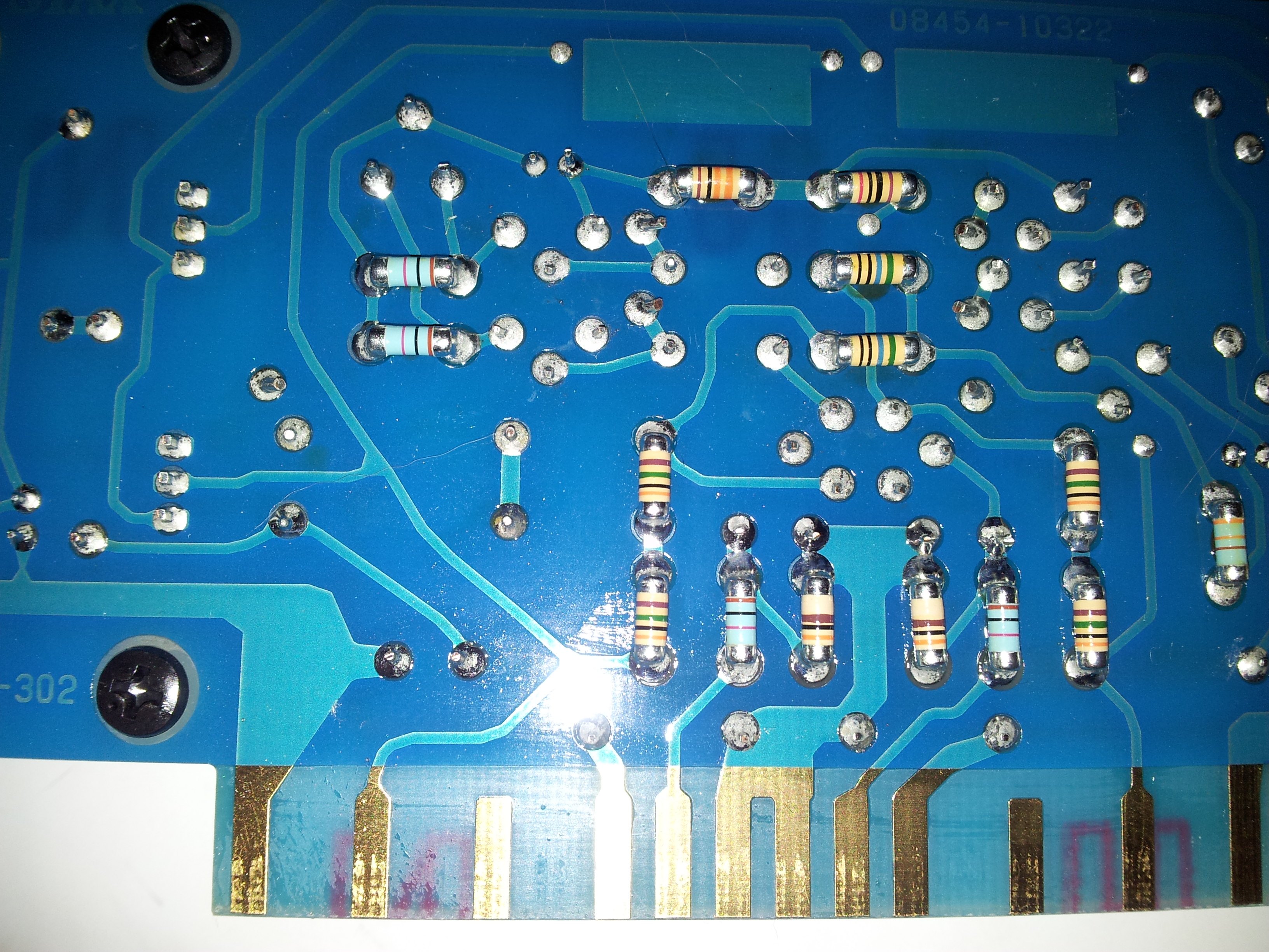
For additional comparisons to Padam's pics, here are a few camera phone pics of my 727II, (quickly) taken before I started my mod.
Irrespective of the ways of modding the 727, I've been listening to mine every day with the SR-007(SZ3), driven by an RA Opus 21, and I think it is a great sounding system; most enjoyable I've owned to date.
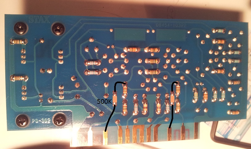
ETA: Found a partial shot of back side of amp board; shows the two referenced resistor pairs


One thing that would really be helpful is pictures of your mods. Can you snap a pic of your amp board the next time you're in your amp?
For additional comparisons to Padam's pics, here are a few camera phone pics of my 727II, (quickly) taken before I started my mod.
Irrespective of the ways of modding the 727, I've been listening to mine every day with the SR-007(SZ3), driven by an RA Opus 21, and I think it is a great sounding system; most enjoyable I've owned to date.
ETA: Found a partial shot of back side of amp board; shows the two referenced resistor pairs
This is getting interesting.

duncan1
500+ Head-Fier
- Joined
- Mar 3, 2012
- Posts
- 724
- Likes
- 33
Yes DRP your second photo shows the two vertical resistors in series on the right -hand side of the photo .They go directly back to the input fets providing neg-feedback and 2 contacts along show the un-connected neg-feedback from the main output ] to the headphones sock] strike that] back towards the same input. As you can see thats where Spritzer connected his 150k resistor to the BOTTOM of the vertical pr. I connected a 500k resistor to the TOP of that pr.You are actually ahead of me as try as I might I cannot obtain a circuit diagram as Stax wont sell me one nor does the Stax dealer have any as repairs are sent back to Japan on 3 months boat journeys I f you could possible send me a copy of the 727-11 circuit I am sure I will be able to add more modifications . While I have good visualization senses and can look over a circuit board and get the gist of a circuit it still is not as good as having the circuit in front of me.This side of the Atlantic they are very secretive in their allowing access to circuits that they want to keep commercially to themselves. for financial reasons. Even my usual circuit company web-site hasn't v got one.This applies especially to the active components as if I can see exactly what they do then maybe be able to change some to better quality as they certainly arent the best quality that you can buy.eg- the 2 2sc1815 bjt which look like a CC source/ current mirror . They are not low noise although they are audio bjt there can be many transistors with the same lettering but ending in different codes [letters/numbers] that change their active quality.-duncan1
drp
500+ Head-Fier
- Joined
- Oct 24, 2003
- Posts
- 699
- Likes
- 11
K, Duncan; thanks for the additional information via PM and email. Reads like your mod is best represented by the following very simple MS Paint edit of the solder side of a 727II amp board. Your stated resistor specs: 500k, .1%, .25 watt, 250v, 5 - 10 PPM. And of course, adjust balance and DC offset for both channels after the amp reaches operating temperature.

Users who are viewing this thread
Total: 3 (members: 0, guests: 3)
