stax srm717/srm727-11
Oct 31, 2015 at 12:07 AM Post #76 of 92
Hi Ducan,
 
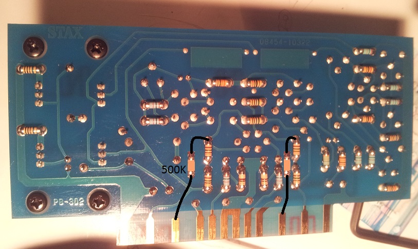
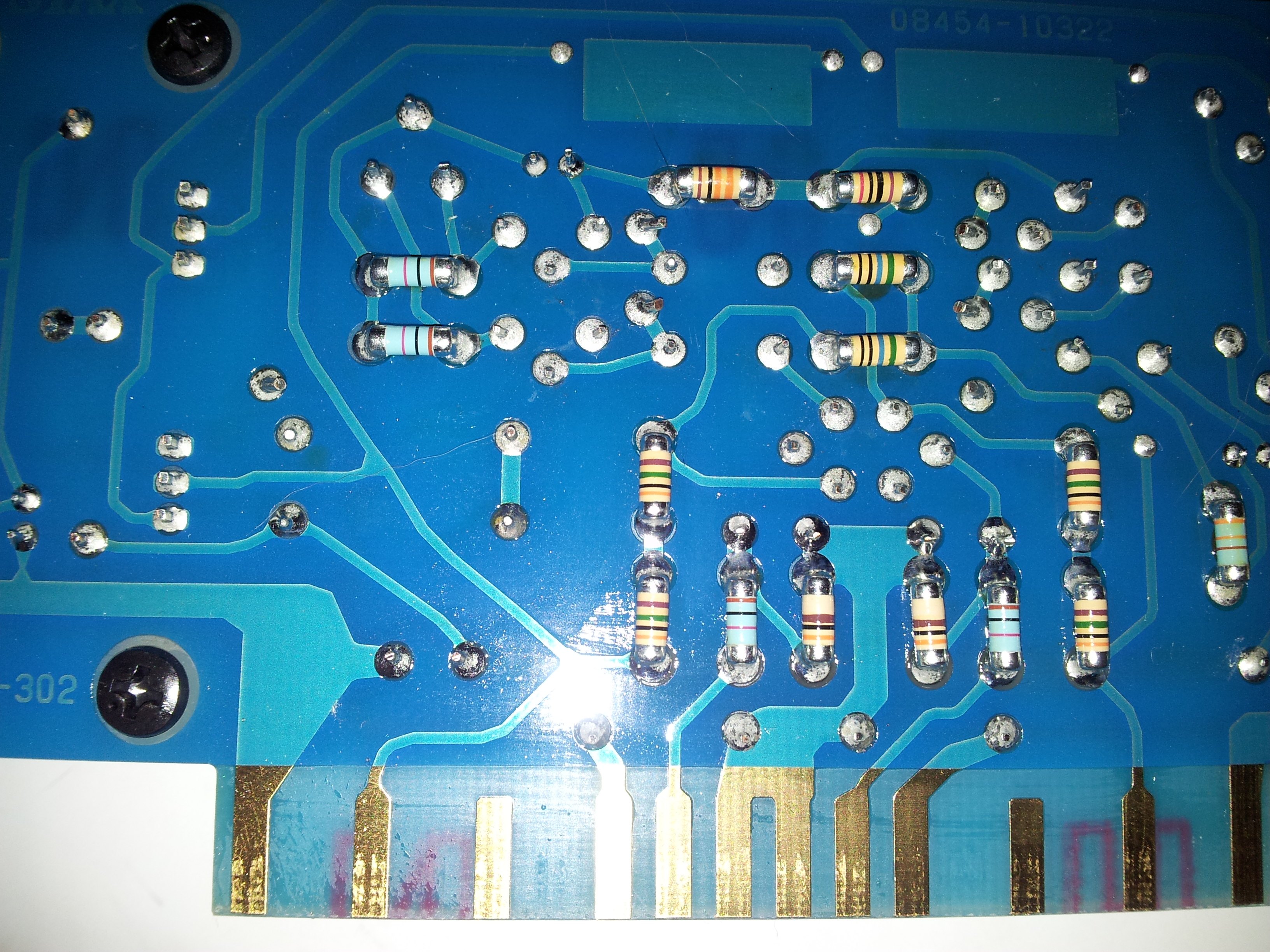
I would like to confirm with you on your final value of the feedback resistor. For soldering of the resistor onto the existing PCB, do I need to de-solder the top smd chip resistor?
 
 
Regards
Tachi.
 
Nov 1, 2015 at 2:40 PM Post #77 of 92
Hello okw3188 Which Perth do you live in ?  Its been a long time since I  posted much on this but are we talking here of the 2 vertical smd  resistors in series  in the feedback in the Stax 727 ? if so I left them as they are but I have now re-instated overall feedback from where the 717  originally had it rather than some local feedback as advertised as -"low feedback                   " to give a "better " sound . .
 
Nov 3, 2015 at 10:29 AM Post #79 of 92
Hello okw3188 the reason I asked about Perth is that I live 50 miles from Perth (Scotland ) I think many Scots settled in your area as ( I am told ) it is like Scotland in certain aspects or maybe just because they liked the area. Anyway I removed my 727 left-hand board to look at it again as it is a while since I worked on it and your right I did change the value of it .Instead of the 150k ohm resistor I replaced it with a  75 k resistor ,now if you have not got one then parallel the top resistor with another lower value one till it equals =75K .This is done to BOTH vertical series feedbacks which you will see spaced apart by four smd resistors . Each resistor must be 250v WORKING as that is the reason for the two smd resistors in series  which total 500v WORKING . As you might think you can replace BOTH smd resistors with even higher quality metal -500v working resistor across both soldering tags on the pcb  the value then being =225k ohm TOTAL .Hope this helps Duncan
 
Nov 3, 2015 at 10:38 AM Post #80 of 92
   Perth is that I live 50 miles from Perth (Scotland )

A fellow scot on Head Fi
eek.gif
what are the odd's of finding another scot on here! I'm from Lanarkshire... Just incase anyone who doesn't know where Scotland is, is wondering...It's scorching  sunshine all year round and never rains
wink.gif

 
Nov 3, 2015 at 11:10 AM Post #81 of 92
Hello Audioholic123 -Yes I was born in Glasgow went to live in Clydebank (as a baby )  came back to Glasgow and now live in a wee fishing village in the East-Neuk of Fife at the moment there is fog and sea mist rolling into the village just like James Herbert,s =The Fog. .Scorching sunshine all year round ? wow !
 
Nov 5, 2015 at 12:12 AM Post #85 of 92
  Hello okw3188 the reason I asked about Perth is that I live 50 miles from Perth (Scotland ) I think many Scots settled in your area as ( I am told ) it is like Scotland in certain aspects or maybe just because they liked the area. Anyway I removed my 727 left-hand board to look at it again as it is a while since I worked on it and your right I did change the value of it .Instead of the 150k ohm resistor I replaced it with a  75 k resistor ,now if you have not got one then parallel the top resistor with another lower value one till it equals =75K .This is done to BOTH vertical series feedbacks which you will see spaced apart by four smd resistors . Each resistor must be 250v WORKING as that is the reason for the two smd resistors in series  which total 500v WORKING . As you might think you can replace BOTH smd resistors with even higher quality metal -500v working resistor across both soldering tags on the pcb  the value then being =225k ohm TOTAL .Hope this helps Duncan

Hi Ducan,
 
After reading your advise, could I confirm with you if I want to replace the 2 x SMD resistor with better quality ones:
 
Desolder the 2 x SMD resistor and connect a total of 225K ohm of resistor (in series and parallel) from the top solder pad of the 2 SMD series resistor to the connect card (gold finger) directly.
 
 
Cheers.
 
Nov 5, 2015 at 2:48 AM Post #86 of 92
You,ve got it  okw3188 -third gold finger/spade in from each side ,same applies to the 717 . If you want the highest quality  remove the two SMD resistors and replace with a single 225K or high quality combination that totals it BUT they must be 500 V working this is very important if you can get a higher voltage - good . The only reason you have two SMD  resistors in series is that they are 250 V working  to a manufacturer production methods save money and fitting all the same types makes live easier as well as "looking good " I am more concerned with audio reproduction . There is no more vital part of any high quality audio amp than the negative feedback the sound quality of the components fitted can make or brake even a high grade amp this applies to any capacitors as well connected in any way to the negative feedback dont skimp .
 
Nov 6, 2015 at 2:54 PM Post #89 of 92
Glad you are happy okw3188 I spent a year or more making modifications to see if they made a positive improvement to the sound quality rather than just a change of tonal quality. I believe the policy of Stax in removing the negative feedback in the 727  was in relation to a fad in the UK of the less negative feedback the more "realistic"  the sound was . While this can be applied to single-ended class A audio output circuits it didnt always work in other cases.Re-instating overall feedback  ie- from input to output in the 727 was for me the correct thing to do.. My mosfet pass transistor power supply I fitted after the fuses is still working fine no blowout from transients switch on peaks  etc I really didnt even need the finned heat sink I fitted as the mosfet doesnt get hot even though I picked a high speed one used in SMPS,s . By fitting it it removed the need to keep changing the supply capacitors as years go by as their influence is greatly reduced and the output has a much reduced mains/ earth noise interference floor level when tested on my scope . A good Stax move in the 727 was fitting heatsinks to the power transistors there were none on the 717 I had to fit my own as they got hot and heat is what you dont want in a solid- state active component when used in an audio circuit as it increases noise..
 
Nov 6, 2015 at 3:15 PM Post #90 of 92
Hi Duncan, 
 
It would be greatly appreciated if you could email me a rough sketch circuit diagram of the MOSFET power supply modification, I will PM you my email address. Thanks a million
smily_headphones1.gif


Users who are viewing this thread

Back
Top