SRM252mod
Mar 26, 2011 at 11:21 AM Thread Starter Post #1 of 33

3210

New Head-Fier
Joined
Mar 22, 2011
Posts
36
Likes
0
Hallo Mark!

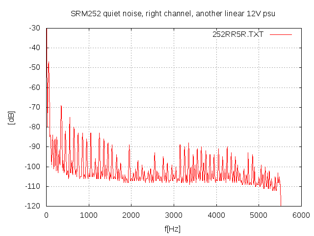
Der umgebaute SRM-252 (siehe Anhang) funktioniert stabil.
Ich habe die vier 300kohm-Gegenkopplungswiderstände gegen 220kohm/2W/MOX getauscht,
dadurch reduziert sich die Verstärkung von 500x auf 345x und der maximale
Eingangspegel erhöht sich entsprechend von 0,59V auf 0,79Veff.
Ddadurch (fast) volle Dynamiknutzung der CD-Quelle und guten Regelbereich
des Lautstärkepotis (12 Uhr ist normal) sowie Erhöhung der
Leistungsbandbreite des Amps von 35kHz auf (zumindest) die 41kHz des SR202.

Weiterhin habe ich noch 2 (parallele) Elkos diekt vor der Hochspannungserzeugung ersetzt
und mit Bypass-Kondensatoren versehen (Murata HighCaps unter der Platine montiert):
33uF/50V/Elko -> 47uF/35V/Tantal/RM5 || 4.7uF/50V/X7R/G1206
1uF/50V/Elko -> 22uF/35V/Tantal/RM5 || 1uF/100V/X7R/G1206

Die somit mehr als verdoppelte Pufferkapazität
gewährleistet für die Hochspannungserzeugung
eine solide Baßleistung, und bei hohen Frequenzen
wirken die Tantalkondensatoren eh besser als Elkos
(durch die HighCaps zudem gut bis in den MHz-Bereich).

Der Baß ist zwar immer noch "flubby" und geht nicht sehr tief (50Hz?),
ansonsten klingt aber alles ok


Mar 28, 2011 at 2:52 AM Post #3 of 33
Thanks AudioCats!
 
You didn't write which volume pot (including switch) will be better and fit.
You didn't write which HV rail caps will be better (lower ESR and/or higher capacitance) and fit.
You ditn't write which else low voltage caps you would repace and with what.
You didn't write why this amp hasn't enough potential to bother with
(isn't it the same circuit as the SRM323 except the power supply?)
But you advice me that this is not the DIY forum.
 
 
Apr 5, 2011 at 2:49 AM Post #4 of 33
I also adjusted the bias offset by reducing the voltage difference of the output with TR2
and reducing the voltage between output and ground with TR1 to below 200mV (DC).
 
Finally I mounted rubber feets (17mm dia, 9mm height) with M3x10mm screws
instead of the taped foam feets below the case.
 
Seems the new version SRM252S uses some different transistors (instead of the SC1968)
and thereby might not work stable with reduced gain. I don't believe so, but it's possible.
I recommend using the tantals (+HighCaps) for stable operation anyway.


Apr 17, 2011 at 3:10 PM Post #5 of 33
I did have a 252 a while back and looked at the circuit a little. This kind of DC output circuit doesn't have too many obvious bottle-necks to improve. I don't see much room to tame its cold/hard sound signature, which was my main complain about the 252.
 
There are quite some spare space in the case, you can try changing the HV caps to film, and change the pot to TKD  (probably need to add seperate power switch). Both should soften the sound a little. 
 
Adjusting the bias is not a good idea, the guys at Stax set the operating point there for a reason.
 
May 9, 2011 at 5:33 PM Post #6 of 33
Seems there exist 22uF HV caps that will fit (height 20mm, diameter 10mm)
and have a higher voltage (350V instead  250V) than the original ones.
Maybe they have a lower ESR and/or will last longer.
 
By comparing the modded 252a with an unmodded one (serial number 1 apart),
the modded one has a tighter bass and sounds more precise, but
the soundstage comes nearer to the listener and the separation of the instruments
sounds less homogen, so the modded one sounds better with pop/electronics than with classics.
Maybe the diaphragm of (at least) the SR202 benefit from less control/feedback at higher frequencies.
This could be the reason for the commonly increased gain of the newer stax amp versions. 
 
The reduction of the gain from 500x to 345x increases the usuable poti range 
by not much more than 1 scale unit, so with a cdp source
I would try gain 250x or when using the SR003 even 200x.
 
Biasing the output of op's to drive them into class-a is common,
but an unsymmetric working balanced output stage is imho to avoid. 
 
 
.
   
 
Dec 25, 2012 at 10:54 AM Post #7 of 33
Quote:
Ich habe die vier 300kohm-Gegenkopplungswiderstände gegen 220kohm/2W/MOX getauscht.


Swapping R11/R12 to 300kOhm to 220kOhm is a bad idea, because output stage has only 1.2mA current sources - 220kOhm will steal almost all of this fragile current, and it's similar impedance to the amp as headphones itself (150kOhm at 10kHz). I'm going to change R11/R12 from 300kOhm to 1MOhm and R5/R6 from 620Ohm to 4k2Ohm. I will let you know.
 
Dec 26, 2012 at 11:50 AM Post #8 of 33
Quote:
 
Swapping R11/R12 to 300kOhm to 220kOhm is a bad idea, because output stage has only 1.2mA current sources - 220kOhm will steal almost all of this fragile current, and it's similar impedance amp as headphones itself (150kOhm at 10kHz). I'm going to change R11/R12 from 300kHz to 1MOhm and R5/R6 from 620Ohm to 4k2Ohm. I will let you know.

 
Ok. I didn't take the limited current capability of the SRM252 into account.
Nice that I heard an improvement (maybe self-biased, or the volume wasn't loud enough to hear the amp aching:wink:.
 
So, with the original 300k feetback resistor and with 130kOhm load (SR202 at 10kHz) the resulting load is 119kOhm (capacively dominated)
and the current at 140Vrms per rail is 1.17mA.
With a 150k feetback resistor and with 360kOhm load (SR003 at 10kHz) the resulting load is 138kOhm (mainly resistive)
and the current at 140Vrms per rail is 1.01mA.
 
=> Reducing the 300k resistor(s) is only possible when using the SR003.
 
I didn't want to change the input stage, so let us know how good Your gain modification works
(even if the little SRM252 seems to get not so much interest here at headfi).
 
Dec 31, 2012 at 4:50 AM Post #9 of 33
I'm still waiting for high quality resistors (and larger capacitors) to finalize this modification. I will keep you posted.
 
For me it's very important to find out if this SRM-252A amp will be worth something or not after these modifications. Stock SRM-252A is disappointing and a can't stand the sound of it even with small and easy to drive SR-003.
 
I wonder if the internal power supply unit [PSU] will survive the leverage of this four 1.2mA current sources to 1.9mA by swapping 4x750Ohm to 4x470Ohm (it's 1.2W more for PSU), and power dispatching (heat) capability from the parts will be still sufficient.
 
Dec 31, 2012 at 2:09 PM Post #10 of 33
Can you post the schematics of the internal psu (with these 750ohm resistors) ?
The HV generation via induction pulses will surely limit the available energy.
May the current be with us. Happy new year!
 
Jan 1, 2013 at 3:14 AM Post #11 of 33
Quote:
For me it's very important to find out if this SRM-252A amp will be worth something or not after these modifications. Stock SRM-252A is disappointing and a can't stand the sound of it even with small and easy to drive SR-003.


The induction pulses could decrease the sound quality by modulating the ground connection (resistive coupling).
Reducing the ground resistance by soldering a wire above it may help.
 
Jan 2, 2013 at 5:02 PM Post #12 of 33
Quote:
Can you post the schematics of the internal psu (with these 750ohm resistors) ?
The HV generation via induction pulses will surely limit the available energy.
May the current be with us. Happy new year!

These 750ohm are R23, R24. Swap to 560ohm or 470ohm on you own responsibility (with constant controlling of the heat of internal transformer and transistors).
My schematics are handwritten at this moment with many mistakes corrected - I have to put it to some tool (like CADSoft Eagle) and verify once again, and present also the alternative version (with all modding applied). Please remind me about this in few weeks (I had a plan to do it anyway).
 
Jan 3, 2013 at 3:33 AM Post #13 of 33
Quote:
These 750ohm are R23, R24. Swap to 560ohm or 470ohm on you own responsibility (with constant controlling of the heat of internal transformer and transistors).
My schematics are handwritten at this moment with many mistakes corrected - I have to put it to some tool (like CADSoft Eagle) and verify once again, and present also the alternative version (with all modding applied). Please remind me about this in few weeks (I had a plan to do it anyway).

 
If the HV capacitors (220uF/250V(?)) are loaded via R23, R24,
reducing their values could have unwanted effects (increasing/reducing/deforming the loading impulse etc.).
I can try some measurements with my digital osco (hope it will survive this), at least to find out if reducing
the 300kohm feetback resistor influences a 1kHz rectangular impulse response (20kHz bandwith limited)
on the amp output when driving the SR003. This may take some time too (February).
 
Jan 5, 2013 at 7:35 AM Post #14 of 33
Quote:
 
If the HV capacitors (220uF/250V(?)) are loaded via R23, R24,
reducing their values could have unwanted effects (increasing/reducing/deforming the loading impulse etc.).
I can try some measurements with my digital osco (hope it will survive this), at least to find out if reducing
the 300kohm feetback resistor influences a 1kHz rectangular impulse response (20kHz bandwith limited)
on the amp output when driving the SR003. This may take some time too (February).


There is no 220uF/250V capacitors inside SRM-252A - you mean 4 x 22uF/250V?
R23, R24 are nothing to do with the power supply section - they set current source's current value: 1.2mA with oryginal 750R and theoretically ~1.6mA with 560R and ~1.9mA with 470R.
 
Jan 5, 2013 at 9:01 AM Post #15 of 33
Quote:
There is no 220uF/250V capacitors inside SRM-252A - you mean 4 x 22uF/250V?
R23, R24 are nothing to do with the power supply section - they set current source's current value: 1.2mA with oryginal 750R and theoretically ~1.6mA with 560R and ~1.9mA with 470R.

 
Yes, 22uF/250V.
I measured the silent noise of the SRM252 (with a silent track from CD) driving the SR003.
It shows significant spikes that could come from the HV generation circuit.


Users who are viewing this thread

Back
Top