SOHA II Builders Thread
Apr 22, 2010 at 7:21 PM Post #1,291 of 1,694
Can you substitute the MC7815 and MC7915 with a different manufacturer? I did a little research and it seems like a standard part and would be safe to find different manufacturer.

I was looking at the MC7815 and MC7915 for the CK2III build and I believe they are back-ordered till September or something crazy like that at mouser.

Fairchild versions:
LM7815CT Fairchild Semiconductor Linear Regulators - Standard
and
LM7915CT Fairchild Semiconductor Switching Converters, Regulators & Controllers
 
Apr 22, 2010 at 7:27 PM Post #1,292 of 1,694
Quote:

Originally Posted by stringgz301 /img/forum/go_quote.gif
Hi all. I'm trying to source parts for a SOHAII and everyone seems to be out of the MC7815 and MC7915 regulators. Mouser, Newark, and Digikey are all out. Are you guys hording them? Any suggestions where to find some?

Thanks in advance.


You can get ST or Fairchild's instead if you omit the "MC". Just note that ST 7915 doesn't regulate without any load. Made me thought the one on my SOHA I was faulty during initial testing.


Observation: I get more noise when I connect earth to ground. There's a ground loop as my USB DAC ground is tied to my LCD monitor's earth.
 
Apr 23, 2010 at 12:44 AM Post #1,293 of 1,694
Quote:

Originally Posted by stringgz301 /img/forum/go_quote.gif
Hi all. I'm trying to source parts for a SOHAII and everyone seems to be out of the MC7815 and MC7915 regulators. Mouser, Newark, and Digikey are all out. Are you guys hording them? Any suggestions where to find some? Are there any alternative parts?

For example, could I use this instead of the 7815 and this for the 7915?

Thanks in advance.


Digi-Key - LM7815CTFS-ND (Manufacturer - LM7815CT)

and

Digi-Key - NJM7915FA#-ND (Manufacturer - NJM7915FA#)
 
Apr 23, 2010 at 1:03 AM Post #1,294 of 1,694
Thanks all.

Regal - the positive one looks good. The negative one you pointed to puts out 1.5A. Should I use that one or this one?
 
Apr 23, 2010 at 10:58 AM Post #1,295 of 1,694
Quote:

Originally Posted by stringgz301 /img/forum/go_quote.gif
Thanks all.

Regal - the positive one looks good. The negative one you pointed to puts out 1.5A. Should I use that one or this one?


They only put out what the amp pulls, so either one.
 
Apr 23, 2010 at 11:25 AM Post #1,296 of 1,694
WIP:


Probably should have gone with a bigger case so I can put the toroid way back. Its enclosure is better at shielding EM than the perforated steel, but it does not cover the bottom of the transformer. Now I have to find some mu metal or something to solve the nasty buzz.
 
Apr 23, 2010 at 12:51 PM Post #1,297 of 1,694
Quote:

Originally Posted by Eokboy /img/forum/go_quote.gif
WIP:


Probably should have gone with a bigger case so I can put the toroid way back. Its enclosure is better at shielding EM than the perforated steel, but it does not cover the bottom of the transformer. Now I have to find some mu metal or something to solve the nasty buzz.


I doubt the transfo is the source of the buzz, mine is as close and silent.
 
Apr 23, 2010 at 5:35 PM Post #1,298 of 1,694
Quote:

Originally Posted by regal /img/forum/go_quote.gif
I doubt the transfo is the source of the buzz, mine is as close and silent.


It is dead silent in the second picture. Only when I mount it on top (the transformer goes inside the black enclosure in the first pic) it buzzes.
 
Apr 24, 2010 at 4:42 PM Post #1,299 of 1,694
Hi all,

As I mentioned in another post, I'm having the same issues with my build as JamesL has. Basicly everything went perfectly until I got to the final step of the initial setup. I can't get 19 V of difference between TB+L and TPL, just a few milivolts.

I've tried with different tubes and got the same results (the measurements below are taken with a pair of new GE 5963 and 6,3 V heather). Also I've replaced Q1L, Q1R, Q2L, Q2R and nothing changed.

I Need to spend some time debugging the amp, but I've taken a few measurements to see if someone has any idea of what's wrong (all the measurements are taken respect ground except voltage drop across R10 and R6):

TB+ = 108,35 V
TL- = -15,152 V
TL+ = 14,873 V
TH = -12,6 V

R10L = 215 mV (voltage drop across resistor)
R10R = 215 mV (voltage drop across resistor)
TPL = 60,1 V
TPR = 60 V
R6L = 394 mV (voltage drop across resistor)
R6R = 392 mV (voltage drop across resistor)
TB+L = 60,4 V
TB+R = 60,3 V

TPL - TB+L = 236 mV
TPR - TB+R = 234 mV

Voltage drop across R4, R3, R2:
R4L = 20,94 V
R4R = 21,3 V
R3L = 203 mV
R3R = 202,6 mV
R2L = 228 mV
R2R = 228 mV

Tubes (GE 5963 with 6,3 V heather)
LEFT TUBERIGHT TUBE
1 = 38,61 V1 = 38,47 V
2 = 0 V2 = 0 V
3 = 3,29 V3 = 3,17 V
4 = -12,59 V4 = -12,59 V
5 = 0 V5 = 0 V
6 = 60,17 V6 = 60,1 V
7 = 0 V7 = 0 V
8 = 3,3 V8 = 3,17 V
9 = -6,27 V9 = -6,23 V

Both opamps measure exactly the same (pin 1 is the one with the dot):
1 = 14,6 V
2 = 0 V
3 = 0 V
4 = -15,15 V
5 = 14,6 V
6 = 14,8 V
7 = 3 V
8 = 0 V

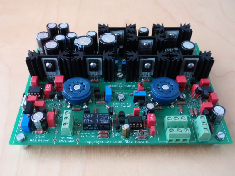
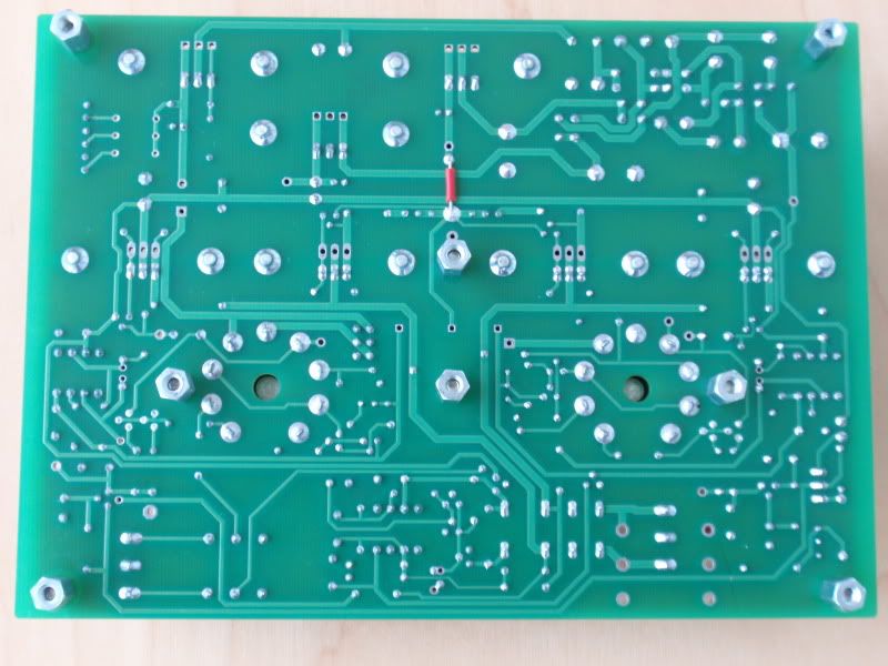
And a couple of pics, just in case they might help:
P4200009.jpg


P4200015.jpg


Thanks everyone!!!!
smile.gif
 
Apr 24, 2010 at 4:58 PM Post #1,302 of 1,694
Quote:

Originally Posted by Alcaudon /img/forum/go_quote.gif
Hi all,

As I mentioned in another post, I'm having the same issues with my build as JamesL has. Basicly everything went perfectly until I got to the final step of the initial setup. I can't get 19 V of difference between TB+L and TPL, just a few milivolts.

I've tried with different tubes and got the same results (the measurements below are taken with a pair of new GE 5963 and 6,3 V heather). Also I've replaced Q1L, Q1R, Q2L, Q2R and nothing changed.

I Need to spend some time debugging the amp, but I've taken a few measurements to see if someone has any idea of what's wrong:

TB+ = 108,35 V
TL- = -15,152 V
TL+ = 14,873 V
TH = -12,6 V

R10L = 215 mV
R10R = 215 mV
TPL = 60,1 V
TPR = 60 V
R6L = 394 mV
R6R = 392 mV
TB+L = 60,4 V
TB+R = 60,3 V

TPL - TB+L = 236 mV
TPR - TB+R = 234 mV

Voltage drop across R4, R3, R2:
R4L = 20,94 V
R4R = 21,3 V
R3L = 203 mV
R3R = 202,6 mV
R2L = 228 mV
R2R = 228 mV

Tubes (GE 5963 with 6,3 V heather)
LEFT TUBERIGHT TUBE
1 = 38,61 V1 = 38,47 V
2 = 0 V2 = 0 V
3 = 3,29 V3 = 3,17 V
4 = -12,59 V4 = -12,59 V
5 = 0 V5 = 0 V
6 = 60,17 V6 = 60,1 V
7 = 0 V7 = 0 V
8 = 3,3 V8 = 3,17 V
9 = -6,27 V9 = -6,23 V

Both opamps measure exactly the same (pin 1 is the one with the dot):
1 = 14,6 V
2 = 0 V
3 = 0 V
4 = -15,15 V
5 = 14,6 V
6 = 14,8 V
7 = 3 V
8 = 0 V


Thanks everyone!!!!
smile.gif


What is the voltage drop across R6 ?
 
Apr 24, 2010 at 5:15 PM Post #1,303 of 1,694
Quote:

Originally Posted by regal /img/forum/go_quote.gif
What is the voltage drop across R6 ?


It's in the post, sorry, I should have been more specific when posting measurements
redface.gif
, I've already edited the post.

R6L = 394 mV (voltage drop across resistor)
R6R = 392 mV (voltage drop across resistor)
 
Apr 24, 2010 at 5:28 PM Post #1,304 of 1,694
R6 current draw is good, which is odd.

Did you check for a short between TPL & TB+L ?

Also buy some SIP sockets to socket all your Q1-Q4 transistors, I think this is going to be a long road to find the answer, luckily the transistors are cheap buy a handful of each.


It looks like your Q1 & Q2 transistors are failing, I beleive they are rated for a max 35V drop, something is causing a greater than 35V drop when you power up after first installing them. Need to find out what that something is. You may have a short to the ground plane which I have seen with many PCBs. I would remove all the jumpers and look for a short to ground in all possible places.
 
Apr 24, 2010 at 5:31 PM Post #1,305 of 1,694
One problem would be that you are running 12v tubes at 6V. Try setting the heater for 12v and see what happens.

Edit: Never mind. I see that you say 6.3V but are actually running at 12V. Off to look at the schematics.
 

Users who are viewing this thread

Back
Top