- Joined
- Oct 10, 2002
- Posts
- 2,941
- Likes
- 1,422
Yes, I agree, the only possible failure here is Q1/Q2. Are you sure that these are BC560 and not BC550?
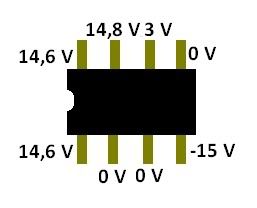
Also, pin 7 of the opamps should be at 15V. Then you have pin 4 at -15V,15V. This is probably a typo. If not, pin 4 should be at -15V on both opamps. But pin 7 not at +15v indicates a problem.
Before you do anything else remove C1 from both channels. Let's decouple the AC just to remove this as a possible transient startup problem.