SOHA II Builders Thread
Jan 5, 2009 at 6:41 AM Post #361 of 1,694
Quote:

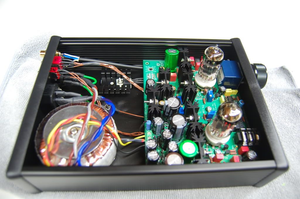
Originally Posted by Arkku /img/forum/go_quote.gif
As an alternative to the “upside down” build, I mounted the tube sockets on a separate platform made from scrap aluminium. It slides into the second highest slot in the Hammond case, which leaves enough room for the stock heatsinks below if the amp itself is in the second lowest slot.

http://www.flickr.com/photos/arkku/3041860978/

See here for how it looks with the lid on—the tubes stick out almost completely. Also very convenient for tube rolling, as I don't have to worry about putting too much pressure on the board.

I think Ferrari also made a similar platform for his other SOHA II build?


Is that the BOM Hammond case? (obviously the short one since you housed the toroid in a seperate enclosure)

So there's not issues with air wiring the sockets to the board? (like picking up interference or anything)

Case work is the hard part for me. I sure wish I could build as well as some of you. I'm not sure I could fabricate that support you and Ferrari mounted the sockets to, so I am inclined to think the "upside down" build will be easier for me. I know some have thought there might be an issue with flexing the board when inserting and removing tubes, but aren't there holes on the board to mount standoffs near the sockets?


Sorry for all the questions. I just finished reading the original thread (47 pages with my preferences hehe). I already read all of this thread and Alex's site. Now that I've decided I'm building this amp, I'm eager to get started, but I have questions about a few parts options. Little things though
wink.gif
Anyway, here they are...

Any DPDT switch should be OK to replace the jumpers, right? Any particular power rating I should look for?

I want to maximize my tube options, so I'm planning to use the more powerful transformer. If I can source the Avel Y236203, will it still fit in the 1455T2202 (the long one) case? I'm planning to put a small DAC inside as well (a BantamDAC for now, perhaps a y1 later).

There has been some talk about using different transistors. Would it be realistic to socket them to make swapping easier? Does it matter if the heatsinks are attached to the board, or can they just be resting there attached to the transistors?

I'm planning to socket the opamp in the e12 circuit based on the suggestion in the other thread. That's all the changes I have in my notes so far
tongue.gif


I want to thank everyone in advance for patience with all my questions. I'm skilled with a soldering iron (worked in manufacturing for many years), but I knew little about what I was soldering. I'm getting there though! I especially want to thank Alex for all the explanations of his circuit design. It has been extremely educational. I understood almost all of it! lol

I sent an email to Jeff already asking about kits and options. Hopefully I can get everything ordered this week and have it built by the end of the month.
 
Jan 5, 2009 at 10:00 PM Post #362 of 1,694
Quote:

Originally Posted by Hayduke /img/forum/go_quote.gif
Any DPDT switch should be OK to replace the jumpers, right? Any particular power rating I should look for?


Well, if you want to run the higher current 6N1P tubes then you need to account for the higher 600ma heater currents. I chose a 2A DPDT switch (panel mount) Mountain DPDT Switch

Quote:

I want to maximize my tube options, so I'm planning to use the more powerful transformer. If I can source the Avel Y236203, will it still fit in the 1455T2202 (the long one) case? I'm planning to put a small DAC inside as well (a BantamDAC for now, perhaps a y1 later).


I sourced my Avel Y236203 trafo right from them (Power Transformers and Power Converters From Avel Lindberg), ~$ 34.00 shipped. Though you'll need to move some components around to make everything fit. For one the rear panel components will need to be all moved over and closer to together. Second with the higher heater currents, you need to provide for cooling for the H- regulator. I mounted mine off board with a heatsink and directly to the case. So that'll eat up the room left for a DAC...

DSC_3339.jpg
 
Jan 6, 2009 at 4:15 PM Post #363 of 1,694
Quote:

Originally Posted by runeight /img/forum/go_quote.gif

To make this worthwhile we need to make at lest ten sets. The price would be $18 for the front panel and $22 for the back panel. This adds $40 to the cost of the kit from GJA.


The case work is always the hardest part and these panels would save a few hours of time, I would be in for two sets.
 
Jan 7, 2009 at 12:12 AM Post #365 of 1,694
Quote:

Originally Posted by Hayduke /img/forum/go_quote.gif
Is that the BOM Hammond case? (obviously the short one since you housed the toroid in a seperate enclosure)

So there's not issues with air wiring the sockets to the board? (like picking up interference or anything)


It's the BOM Hammond case, but actually the longer one since I built my entire amp on protoboard, made the high-current heater, used larger than stock heatsinks, added a crossfeed, multiple outputs and inputs, etc. So, mine just took more space. But the height of both cases is the same. =)

I doubt the air wiring is of any consequence; after all, it's just an inch or so. Classic tube amps often have a lot more air wiring.


Quote:

Originally Posted by Hayduke /img/forum/go_quote.gif
Case work is the hard part for me. I sure wish I could build as well as some of you. I'm not sure I could fabricate that support you and Ferrari mounted the sockets to, so I am inclined to think the "upside down" build will be easier for me.


If you are already going to make the holes for the tubes on the top of the case yourself, doing the elevated platform only requires drilling an additional set of holes for the tube sockets. Of course, there's the cutting of the plate to be used as the support, but it isn't very precise work (won't show outside anyhow). I took mine from a scrap piece of aluminium profile.

That said, the upside down approach is easier still, I just prefer this way. =)
 
Jan 7, 2009 at 1:08 PM Post #366 of 1,694
Quote:

Originally Posted by bmwpowere36m3 /img/forum/go_quote.gif
Can anyone recommend some "bumpers" or pads to stick under the Hammond enclosure. The included ones are fairly short, ideally something from Digi-Key.


I usu just get something from hardware store (e.g. HD has a lot of options)...
If you want something large & fancy, I've used Elegant Anodized Aluminum ones
smily_headphones1.gif
 
Jan 8, 2009 at 11:33 PM Post #367 of 1,694
i have the tube sockets from jeff r's kit and they have a metal rod i think where the led to light the tube would go. how do i remove this?

The part is from cascade surplus
 
Jan 9, 2009 at 12:46 AM Post #368 of 1,694
also i am confused on mounting the devices to the heat sinks. I have placed the "sticker" isolator on the heatsinks. Now i put the devices with the labels facing away from the heat sinks which brings me to the confusing part. I am not sure where to place my washer, under the screw head on the front of the device or against the back of the heatsink before the nut.
 
Jan 9, 2009 at 12:57 AM Post #369 of 1,694
lacrossbowe8, I am, unfortunately, in a meeting right now and can't adequately help. I should be through in about an hour and a half. Perhaps someone else will offer help in the meantime. If not, I'll be back . . .
 
Jan 9, 2009 at 1:41 AM Post #370 of 1,694
There should be two washers, a plastic shouldered one and a metal one. The metal one goes on the backside of the heatsink. The plastic on the front side of the transistor. The screw will come in contact with the heatsink. The plastic shouldered one is to keep space between the screw and the transistor, to isolate the transistor completely. The direction of the screw doesn't really matter. I use whatever has more space for where I put it.

If you are using plastic enclosed transistors (stock BD139 for example) then it doesn't matter. The hole on the plastic transistor is smaller. I keep the plastic shouldered washer on it, so I don't lose it, but it won't fit in the hole. I flip the shouldered washer around. It's fine.
 
Jan 9, 2009 at 2:04 AM Post #371 of 1,694
Quote:

Originally Posted by holland /img/forum/go_quote.gif
There should be two washers, a plastic shouldered one and a metal one. The metal one goes on the backside of the heatsink. The plastic on the front side of the transistor. The screw will come in contact with the heatsink. The plastic shouldered one is to keep space between the screw and the transistor, to isolate the transistor completely. The direction of the screw doesn't really matter. I use whatever has more space for where I put it.

If you are using plastic enclosed transistors (stock BD139 for example) then it doesn't matter. The hole on the plastic transistor is smaller. I keep the plastic shouldered washer on it, so I don't lose it, but it won't fit in the hole. I flip the shouldered washer around. It's fine.


Like Holland said, if your using the BOM transistors (BD139) then are already "isolated" and the little isolating, shouldered washer doesn't really fit in. I just set it aside and installed it like this: Screw > Transistor > Heat Pad > Heatsink > Flat Washer > Lock Washer > Nut
 
Jan 9, 2009 at 3:34 AM Post #372 of 1,694
Yippie!

I just received today my SOHA II kit from Glass Jar Audio. Add it to some alternative parts from BD (Toshiba 2SC3422), Digikey (Panny FC/FM), pcX (Mundorf M-CAP Supreme, upgraded RCA jack and Sylvania 12AU7) I'm now ready to start my build. Just missing Amperex orange globe 6DJ8 and I'll be ready for some tube rolling.

I just noticed that the Mundorf caps are much bigger than what I expected and their leads larger than PCB holes. It will need some creative soldering.

DCP_1543-vi.jpg


DCP_1546-vi.jpg


DCP_1550-vi.jpg


Guess what I gonna do with my free time this weekwend?
biggrin.gif


Cavalli Audio SOHA II album | Wolf18t | Fotki.com
 
Jan 9, 2009 at 6:39 PM Post #374 of 1,694
Quote:

Originally Posted by runeight /img/forum/go_quote.gif
smily_headphones1.gif
And you will keep us informed of progress?


For sure I will, and with some progress pictures. I'll keep my camera not to far from the workbench.
wink.gif
 
Jan 9, 2009 at 6:45 PM Post #375 of 1,694
OK, I've thought about it some more and I don't want the tubes to stick out of the case so much. I'm going to just build that part normally.

I still have a question nobody responded to though. Some folks have talked about sound differences using different transistors. What are your thoughts on socketing them? Is it important that the heatsinks are soldered to the PCB? I'm thinking it won't really matter. Or is the difference so small that it's not worth the effort?
 

Users who are viewing this thread

Back
Top