SOHA II Builders Thread
Jan 9, 2009 at 7:54 PM Post #376 of 1,694
Quote:

Originally Posted by wolf18t /img/forum/go_quote.gif
Yippie!
...
I just noticed that the Mundorf caps are much bigger than what I expected and their leads larger than PCB holes. It will need some creative soldering.


Good sounding caps are somtimes a bit big(ger), but with some creativity it can be done.
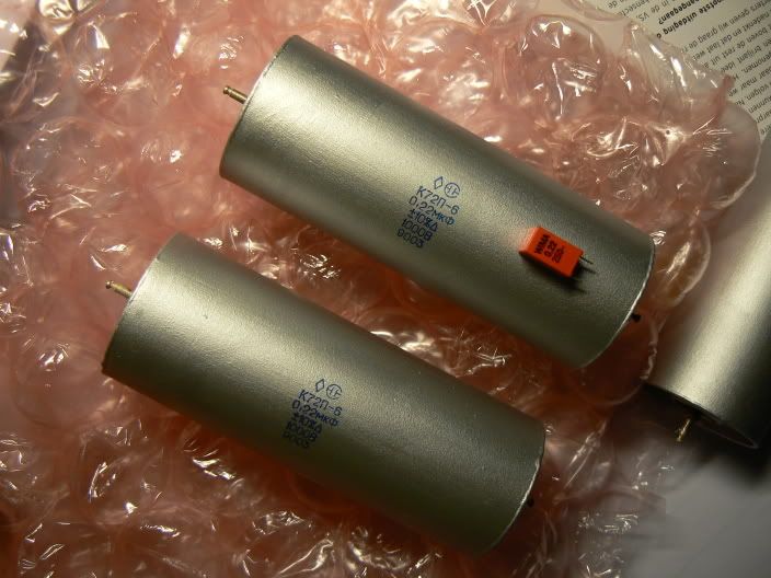
I also under-estimate the size of the Teflon caps I want to use in my amp...
smily_headphones1.gif


Afbeelding590.jpg


(The stock Wima MPK on top for size comparasion).
 
Jan 10, 2009 at 12:41 AM Post #377 of 1,694
Quote:

Originally Posted by Ferrari /img/forum/go_quote.gif
Good sounding caps are somtimes a bit big(ger), but with some creativity it can be done.
I also under-estimate the size of the Teflon caps I want to use in my amp...
smily_headphones1.gif


(The stock Wima MPK on top for size comparasion).


LOL, these are huge caps! They merit to be shown through amp top panels holes. Just beside the tubes.

Anyway that's something I'm considering now on my build. I think the Mundorf are quite nice looking.


Quote:

Originally Posted by Hayduke /img/forum/go_quote.gif
I still have a question nobody responded to though. Some folks have talked about sound differences using different transistors. What are your thoughts on socketing them?


Never done it or see it done by someone either.

Keep in mind that every time you will change a set, you will need to re-bias them. You will maybe also have problem mounting them on the heatsinks, if the screws don't align with holes.
 
Jan 10, 2009 at 1:55 AM Post #378 of 1,694
Quote:

Originally Posted by wolf18t /img/forum/go_quote.gif
Never done it or see it done by someone either.

Keep in mind that every time you will change a set, you will need to re-bias them. You will maybe also have problem mounting them on the heatsinks, if the screws don't align with holes.


Holland rolls output transistors. He supplied me with a scoket part number, but I can't recall if it was on aHead-Fi thread or during the prototype discussions...
 
Jan 10, 2009 at 2:25 AM Post #379 of 1,694
Quote:

Originally Posted by wolf18t /img/forum/go_quote.gif
Never done it or see it done by someone either.

Keep in mind that every time you will change a set, you will need to re-bias them. You will maybe also have problem mounting them on the heatsinks, if the screws don't align with holes.


There shouldn't be an issue with the holes not lining up. I'm thinking of the transistor and the heatsink being a unit that I "plug in" to the board. So swapping them out would mean I unplug the sub assembly, then take the screw out that holds the transistor to the sink, then attach the new transistor. So it won't be quite as easy as rolling a tube, but easier then soldering
wink.gif


Quote:

Originally Posted by wiatrob /img/forum/go_quote.gif
Holland rolls output transistors. He supplied me with a scoket part number, but I can't recall if it was on aHead-Fi thread or during the prototype discussions...


Really? I have read both SOHA II thread on head-fi and the one on headwize. I'll go look again. Thanks

So apparently it can be done fine, huh? I was worried because I had never heard of anyone using a socket with a transistor.

The deviations from the original design I want to implement are:
1. Socket the transistors.
2. Put a DAC inside the case and use a switch to select the input.
3. Use a switch instead of the jumpers for the heater voltage.
4. Use the larger toriod to support 600ma tube heaters.
5. Use a dual color LED on the e12 delay circuit.

If anyone has any advice on potential issues with any of these, I'd appreciate it. I think I understand the effects of these changes, but I might be missing something.
1. See my previous posts
wink.gif

2. This should be pretty straight forward with a DPDT switch. Planning to use a BantamDAC (at least to start).
3. Easy to implement and already discussed.
4. I just need to get a 1.5a transformer. Any other part changes needed? I also realize this may make it harder to fit the DAC in the Hammond case.
5. This has been discussed, and Alex already posted the schematic to use. I don't anticipate any issues with this change.

Are there any other things I can do to improve the amp? I'm considering different caps, but my understanding is that this mostly benefits coupling caps and this amp doesn't use them. Am I way off here?

I was hoping to get my parts ordered this week, but work was too busy. I'm planning to finalize my BOM this weekend and order on Monday.

Thanks in advance for everyone's help
smily_headphones1.gif
 
Jan 10, 2009 at 3:56 AM Post #381 of 1,694
Thanks Holland
smily_headphones1.gif


That's what I'll use. Did you socket all the transistors? If not, which ones?
 
Jan 10, 2009 at 2:46 PM Post #382 of 1,694
Quote:

Originally Posted by wolf18t /img/forum/go_quote.gif
LOL, these are huge caps!


Yes, those Teflon caps are indeed huge.
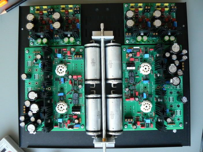
To make things fit nicely, I have downsized the inter-stage coupling caps of my amp a bit.
very_evil_smiley.gif


Afbeelding592.jpg
 
Jan 10, 2009 at 3:55 PM Post #383 of 1,694
oooh , that is looking phenomenal , balanced SOHA II with exquisite attention to build detail (as always).

Quote:

Originally Posted by Hayduke /img/forum/go_quote.gif
The deviations from the original design I want to implement are:
1. Socket the transistors.
2. Put a DAC inside the case and use a switch to select the input.
3. Use a switch instead of the jumpers for the heater voltage.
4. Use the larger toriod to support 600ma tube heaters.
5. Use a dual color LED on the e12 delay circuit.


1. - the only issue is the weight of the heatsinks , you would need to screw them down as you noted
2. I did this with an alien - I would recommend a separate power supply to avoid the chance of hearing nasty pc generated noise. I hooked up a simple 5V regulator that I pulled from the LV and it works a treat.
3. the switch is the default recommendation - I am sure someone has the part number and I thought it was part of the BOM - it is a board mount dpdt
4. & 5. make sense - not sure how to implement 5, have a look at this thread to see if you can mod the layout.

..dB
 
Jan 10, 2009 at 4:43 PM Post #384 of 1,694
Ferrari, you just continue to do one beautiful amp after another, no matter which one it is. Will you design enclosures for me?
o2smile.gif
 
Jan 10, 2009 at 7:46 PM Post #385 of 1,694
Quote:

Originally Posted by runeight /img/forum/go_quote.gif
Ferrari, you just continue to do one beautiful amp after another, no matter which one it is.
o2smile.gif


Without creative designers like you and amb, that would be impossible, to be honest.
Trying to build amps with some love and dedication is my way to say: “thank you guys, I appreciate your hard work”.
smily_headphones1.gif
 
Jan 10, 2009 at 10:44 PM Post #386 of 1,694
Update:

Well, I finally got some more time to work on it. Things are looking much better. My headphone jack diagnosis from before was incorrect, I was using some really crappy headphones that must have a short somewhere. So when I was moving the headphone jack around it must have fully shorted the sound into both channels. Anyways I found a bad solder joint (grrr) on the pot between it and the left input. So that's fixed now, and I have sound in both channels
smily_headphones1.gif


As far as I can tell everything sounds like it should, even though P2 on both channels are still at the end of their travel. I don't hear the distortion from before and the e12 isn't tripping, I assume that's because I'm not shorting the output anymore. I double checked the resistor's and can't find anything wrong, I also replaced Q8 on the left side and it didn't change anything. Should I try replacing Q7?
 
Jan 11, 2009 at 4:59 AM Post #387 of 1,694
Yes, I think you'll have to make your way through the O/P transistors one at a time. First Q7 then Q6 then Q5 until you solve the problem. Because you should be able dial up 100mA on each channel.
 
Jan 11, 2009 at 6:15 PM Post #388 of 1,694
Woo hoo, I finished my build this AM. And am now listening to some hot jazz on a cold nasty day. Now to finish the casing, but somebody will have to pull the cans off my head first.

Somebody used VitaQ instead of Wimas on C1. HOw does it compare with the WIMAs in this amp?
 
Jan 11, 2009 at 7:41 PM Post #389 of 1,694
Quote:

Originally Posted by rhester /img/forum/go_quote.gif
Woo hoo, I finished my build this AM. And am now listening to some hot jazz on a cold nasty day. Now to finish the casing, but somebody will have to pull the cans off my head first.

Somebody used VitaQ instead of Wimas on C1. HOw does it compare with the WIMAs in this amp?


I ended using VitQ's in the C1 L/R positions, but I also chose to use "boutique" caps in other sections as well. I say the amp sounds wonderful and has great synergy with my Senn HD580's. However I can't compare it to the sound of the stock Wima's, just for that position: my SOHAII build

I'm curious has anyone listened to Grado's with this amp, specifically SR-80's. Yesterday I auditioned a pair of SR-80's and RS1 at an audio shop with their Grado RA1 amp. I got to take a pair of SR-80's back home for more auditioning with my setup (iMod DAC, SOHA II) and honestly the SR-80's aren't sounding too good. In the store, IIRC, they sounded pretty decent... yet different from my 580's.

At home, their pretty grainy, at time harsh treble, and peaky in the mid-bass and upper-mid treble... so details I hear in the HD580's are lost in the very projected, in your face sound.
 
Jan 11, 2009 at 8:59 PM Post #390 of 1,694
Quote:

Originally Posted by rhester /img/forum/go_quote.gif
Woo hoo, I finished my build this AM. And am now listening to some hot jazz on a cold nasty day. Now to finish the casing, but somebody will have to pull the cans off my head first.


Ask the wife for help!
wink.gif

Congrat with your amp, btw.
beerchug.gif
 

Users who are viewing this thread

Back
Top