simple Dc supply - meter lying to me?
Feb 4, 2009 at 9:09 PM Thread Starter Post #1 of 16

adamus

500+ Head-Fier
Joined
Feb 29, 2008
Posts
939
Likes
74
Hi,

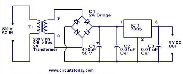
I just built a very simple supply for some input switching boards.

paralelled secondaries of a 9-0-9-0 transformer. Bridge rectified. 1000uf cap to ground.

measures about 13vdc.

however, when i measure the ac voltage on ouput.... my meter says 34VAC. tried another meter, same result.

any idea how this is happening?
 
Feb 4, 2009 at 9:45 PM Post #3 of 16
Try putting a cap in series with one of the meter leads. My Protek 608 works great EXCEPT for AC voltage measurements. Was measuring the ripple on a tread and couldn't figure out why the meter was reading several volts AC, but the scope showed nothing.
 
Feb 4, 2009 at 9:55 PM Post #4 of 16
schematic could not be simpler - its a simple bridge, with one 1000uf cap to from + to -.

ac only meaures + to neg, not the other way round..... how bizarre. surely this is a meter error, but 32v seems a big old error.

Not wanted to draw the schematic, its exactly the same as this, but just delete everything past the first cap (Which is 1000uf in mine)

5v-regulator-using-7805.JPG
 
Feb 4, 2009 at 10:27 PM Post #7 of 16
Where would the DC offset be coming from on a power transformer secondary before the bridge rectifier? I built pretty much this same thing this weekend and have 24VAC from the transformer secondary and 34VDC after rectification and smoothing. The only thing I did differently was place a 100k ohm resistor across the lines to discharge the cap when power is disconnected. It should also be noted that I'm able to read those voltages with a $4 harbor freight multimeter. I confirmed it's reading accurately by my good multimeter before starting that project.

An unloaded non-switching power supply(such as just using a transformer, rectifying the AC to DC, and using a cap to smooth the power out) without regulation should have more DC when unloaded than AC. When fully loaded the DC and AC should almost match. Disconnect everything from the transformer and see what it it putting out uncoupled to anything. Then, check to make sure the rectifier is doing its job before reconnecting the transformer.

You said it was reading AC from positive to negative but not the other way around, AC isn't polarized, it shouldn't matter which way you are measuring you should get the same reading. Where are you measuring AC from with the circuit together? Are you sure you didn't connect the rectifier with the DC outs actually being your AC in? Not sure how experienced you are with these but the wavy lines on the chip indicate AC in and the + - are your DC outs.(Not intending to talk down to you, just good to check everything)
 
Feb 5, 2009 at 6:58 AM Post #10 of 16
DK - i am pretty experience, built a lot. not up to amb standards yet though........

yep - loaded it, tested it.

AC isnt polarised, yet flicking the probes round means i either measure 34vac, or 0VAC. more evidence to suggest meter?

more evidience to suggest the meter lying, how would it genereate 34Vac, from 9v supply, which even when unloaded is only producing around 13vdc.

exact trace of circuit.

powersupplyfj7.jpg
 
Feb 5, 2009 at 10:02 AM Post #11 of 16
Quote:

Originally Posted by DKJones96 /img/forum/go_quote.gif
Where would the DC offset be coming from on a power transformer secondary before the bridge rectifier?


If you look at adamus' schematic, you'll see that when you put the meter across the transformer's secondaries, it's also across the smoothing cap. You cannot help but be measuring the rectified and smoothed voltage. To measure the transformer only, you have to disconnect it from the bridge.

Quote:

Originally Posted by adamus /img/forum/go_quote.gif
AC isnt polarised, yet flicking the probes round means i either measure 34vac, or 0VAC. more evidence to suggest meter?


Yep.
 
Feb 5, 2009 at 3:06 PM Post #12 of 16
Forgive me for dragging this on, but the way I understand a full-wave rectifier working you can't read across the cap through it.

rectifiedpower.gif


The only way to get power from the DC side of the rectifier to the AC side is via the negative side and even when you do there is no bias because the negative connects to both sides of the secondary. It's like trying to read DC volts from a battery while only probing the negative terminal.

If you are able to read a DC voltage on the AC side of the rectifier you have a bad diode.

Please correct me if I'm wrong.
 
Feb 5, 2009 at 4:45 PM Post #14 of 16
would love it to be mVAC - but the reading is in VAC.

i think i am with tangent and AMB on this one, has to be the meter.
 
Feb 6, 2009 at 1:05 AM Post #15 of 16
Quote:

Originally Posted by DKJones96 /img/forum/go_quote.gif
Forgive me for dragging this on, but the way I understand a full-wave rectifier working you can't read across the cap through it.


No doubt my explanation is missing something, but the effect is the same as if what I wrote is precisely true: disconnect the transformer from the bridge, and your reading will start making sense again.
 

Users who are viewing this thread

Back
Top