Roll Call: Who's building, built, or thinking of building a beta22?
Mar 28, 2010 at 10:27 PM Post #2,626 of 3,218
Quote:

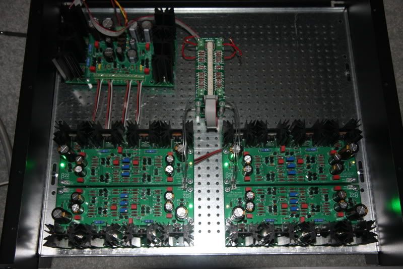
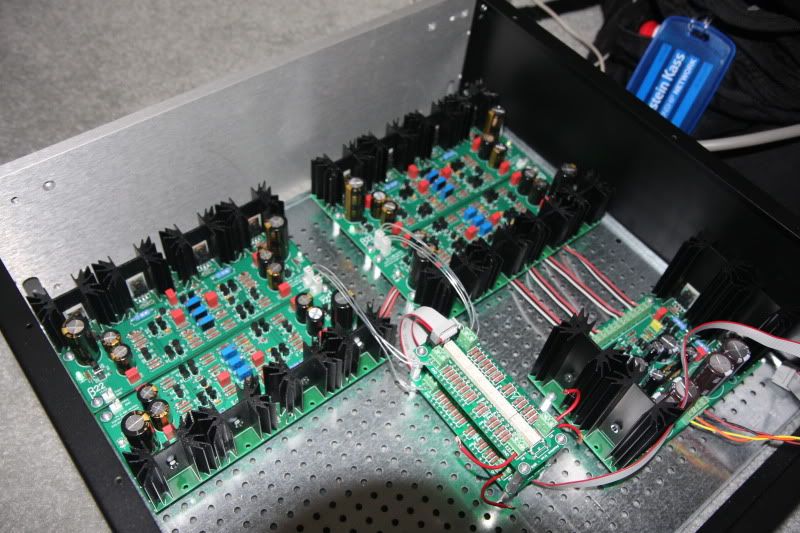
Originally Posted by swt61 /img/forum/go_quote.gif
Very nice quattro98!

Here are a few pics of my own β22. It's a four channel, with dual σ22s in a separate enclosure. There were many hands involved with this project...luvdunhill, N_Maher & fierce_freak. The Top unit is a fully balanced TPA Darwin source selector with six balanced inputs, two balanced outputs and a balanced loop out. The cases were built by me, and are figured Black Cherry w/a five coat, modified Tung Oil finish.


Nice work, really impressive.
 
Mar 29, 2010 at 12:46 AM Post #2,627 of 3,218
Would someone do me the favor of a quick sanity check for the transformer?
Quote:

Originally Posted by s22 lower limit
Lowest wall voltage I'm likely to see = 110v
Rated voltage with 1A draw @ 120v = 24.3v
maximum forward voltage (d1+d2) = 0.975v *2

(24.3v * 110/120 * root2) - 1.95v = 29.6vdc unregulated


I plan on setting it to regulate at 25v and if I did the calculations correctly, ~1.8w dissipated per s22 mosfet, and ~2.7w per b22's cascode mosfets (under normal conditions).
 
Mar 29, 2010 at 4:35 AM Post #2,628 of 3,218
The heat dissipation numbers are all comfortable as long as your case will be ventilated. But whether any of these numbers are realistic or not depends on the load behavior of your transformer.
 
Mar 29, 2010 at 9:49 AM Post #2,629 of 3,218
The load behavior is specified on the datasheet and is factored into my calculations, but I do not know for certain until I test it.

The top of my case will be well ventilated but it is a rather small chassis, so I am trying be less wasteful; keeping the transformers output close to b22's operating voltage but without compromising regulation.

What is the total diode drop? My understanding is <~2v per rail, but I wasn't sure.
 
Mar 29, 2010 at 1:08 PM Post #2,630 of 3,218
Quote:

Originally Posted by JamesL /img/forum/go_quote.gif
What is the total diode drop? My understanding is <~2v per rail, but I wasn't sure.


Depends on the diode you use. You can look at the datasheet and check the Vf spec, and multiply by 2 to get a rough estimation for a full-wave bridge.
 
Apr 4, 2010 at 9:45 PM Post #2,633 of 3,218
IT"S ALIVE

IMG_1422.jpg

IMG_1423.jpg


Note nothing is pinned down yet. I think i am going to keep the B22 boards oriented that way. The Sigma22 i may move it farther back

well i know it works. Still got a long way to go. I figured i might as well test it to make sure it works before i decide to go all out on the CNC work in the upcoming months. got all the DC offset to zero. 4.5v through the input stage, and set VR2 down to 55mV

I don't really know how it sounds yet i only tried 1 side at a time. There was a very slight hum (barely audible), but i think it is from the transformer (right next to everything) and probably the very messy job i did of clipping everything together for the bench test.

My transformer definitely hums audibly if i put my head near it. The trafo itself gets about 140F on my temp gun with the lowered Qcurrent. I lowered the Qcurrent/vDrop down to 55mV per board and the temps are much better on the Sigma22 and B22 Mosfets.

i cant wait to listen to it. i have my XLRs with the zobels soldered to the back. I am ready.
 
Apr 6, 2010 at 6:46 AM Post #2,634 of 3,218
I am having a strange issue with my beta right now. Over time, while I am listening, the right volume sort of dies away and eventually disappears completely. I have isolated the amp as the cause by unplugging/changing everything else in the chain, but the amp tests perfectly on all channels. I havent been able to isolate any bad wiring, but wiring would seem to cause intermittent issues.

What could be causing this? Any ideas on what I should be looking for. The PS tests perfectly as well.
 
Apr 6, 2010 at 10:26 AM Post #2,635 of 3,218
tintin47, it does seem like bad wiring/contact. Use your DMM and start checking the continuity between the input jacks and the volume pot, and from the pot to the amp boards, and from the amp outputs to the headphone jack contacts.

Also, check your interconnect cables and try a different source and a pair of headphones to see if the problem is external to the amp.
 
Apr 6, 2010 at 3:16 PM Post #2,636 of 3,218
tintin47- you may want to also go over the amp board for that channel and check all of your solder joints. Perhaps as the amplifier heats up over time (while cased up) something gets warm enough to shift a little.
 
Apr 7, 2010 at 3:45 AM Post #2,637 of 3,218
Will do. I absolutely know the problem is confined to the amp. It has happened on multiple headphones with multiple interconnects and two sources. I think that anonanimal may be on to something with the idea it is heat-related. I will just start going over the whole thing when I have some time.

This only started happening after I took it to the boston meet. Most likely I just havent found the jostled wire yet.
 
Apr 8, 2010 at 5:21 PM Post #2,638 of 3,218
I'm currently finalizing my build before ordering the enclosure but I'm encountering some difficulties with the use of my momentary switch (shurter illuminated).
Things are getting fuzzy on how to wire this thing. I do have built an e24 but it seems to require its own toroid (that I forgot to order....). Start to be cumbersome having an e24+relay+toroid just to make my switch work, no ?
On the other side, on the Krmathis build, the team has used what appears to be an AC relay directly connected to the switch.
Basically, what's the "simplest" way to connect this kind of switch ? I'm aiming at having a very compact case so space matters
smily_headphones1.gif

Sometime I feel dumb dumb... I managed to build up the amp and PSU without a glitch but am blocking on the switch....
Thanks
 
Apr 8, 2010 at 5:36 PM Post #2,639 of 3,218
If you want to use a momentary switch, the e24 circuit is required. The e24 takes a single pulse from the momentary switch and then holds the relay open or closed until it receives another pulse from the switch. The e24 circuit does require transformed AC however the s24 from AMB allows the usage of a very compact EI-30 transformer to power the e24. The s24 board is the same size as the e24.

In the group build, a latching switch was used and subsequently the e24 circuit was not required. The push button switch "stays in" when it is pushed, providing a constant current to the relay coil, keeping the power supply on. Pushing the button again returns it to its original position and shuts off the relay.

Using a latching push button switch is somewhat simpler because it doesn't require the e24 driver circuit and the associated transformer. However if you already built an e24 and you have the momentary push button, you just need a small transformer. The s24 board and components are fairly inexpensive so its actually not that much more complicated to use the e24 and the s24 and e24 can stack for a compact footprint. Both options do require the use of a relay.
 
Apr 8, 2010 at 11:04 PM Post #2,640 of 3,218
Thanks for your explanations and for pointing me toward the s24... seems to be the most compact solution for me. I won't change my switch for a latching one since it already cost me some $$. I'll gonna waste some more money with shipping fees for pretty cheap components but I start to get use to it since I started this project. Hopefully the end is near !
 

Users who are viewing this thread

Back
Top