Roll Call: Who's building, built, or thinking of building a beta22?
Mar 27, 2010 at 3:10 PM Post #2,611 of 3,218
Quote:

Originally Posted by johnwmclean /img/forum/go_quote.gif
You might have to dig into the troubleshooting pdf and do some voltage measurements.


I figured that much, I just don't know where the most logical place is to start.
 
Mar 28, 2010 at 12:17 AM Post #2,612 of 3,218
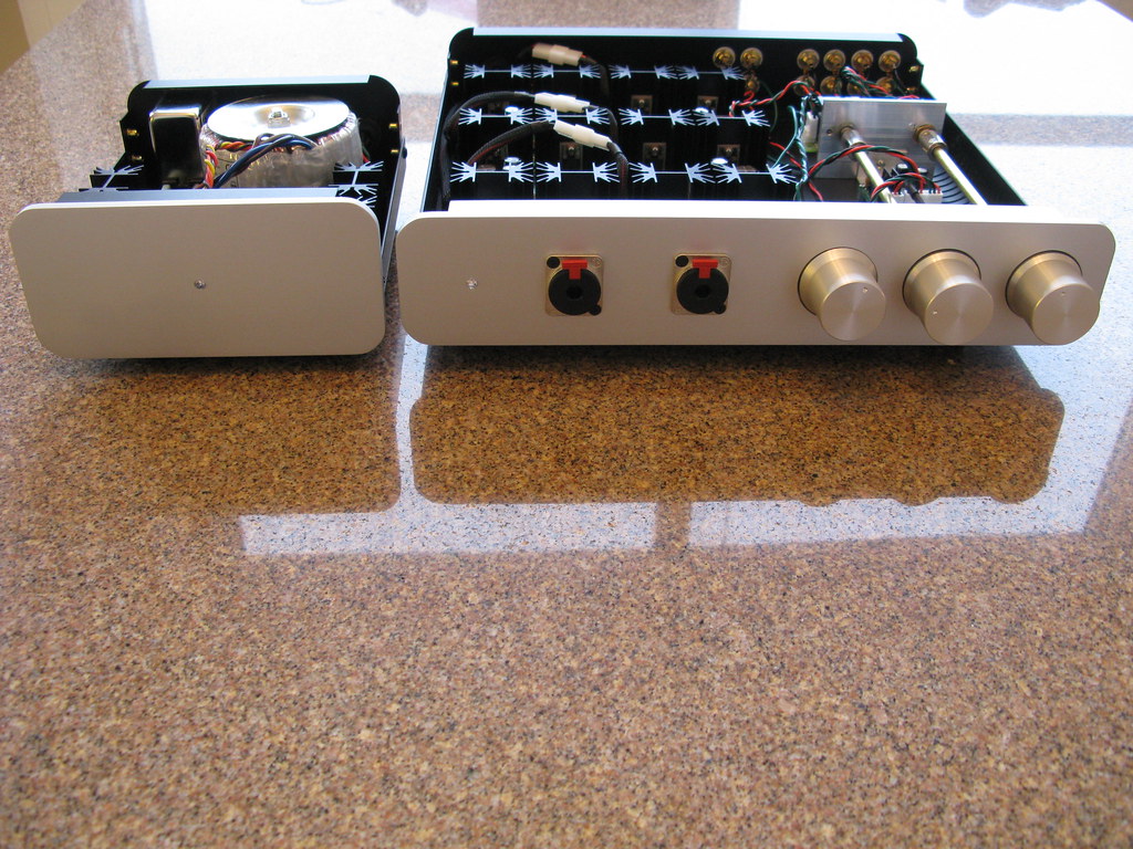
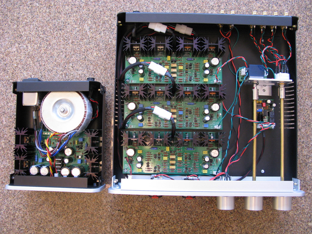
I started this a few years ago & then was too busy to finish it. Recently, I decided it was time to get it completed. This is my first true DIY project (although I have plenty of experience soldering & using a multimeter). I'm excited by how well it turned out.

The chassis is from ATI Research. I sent them files for the face plates & they did the machining & provided the knobs. Unfortunately, I understand they're no longer in business. The left-most knob is a headphone-preamp-out switch, the middle one is the volume control, & the right-most knob is for the input selector. Originally, the left-most knob was meant for a Tangent crossfeed circuit, but I decided to omit it, but I already had the faceplate machined for the 3rd control, so I added the switch. It comes in handy to disconnect the front panel jacks when changing headphones without powering off the amp.

I would like to thank Ti Kan (AMB), Jeff Rossel (Glassjar), Arthon (ATI), & all of the contributors at Headwize & Head-Fi. I was able to find answers to all of my questions in the various support threads which made this possible.

The amp sounds amazing & I'm sure it will make a great pre-amp if I want to use it to setup a 2 channel system.

4467781107_615f914fe4_b.jpg


4467775895_1743ac3795_b.jpg


4467777597_5608b94e37_b.jpg


4467779317_ec4ee963c8_b.jpg
 
Mar 28, 2010 at 2:27 AM Post #2,614 of 3,218
Quote:

Originally Posted by quattro98 /img/forum/go_quote.gif
I started this a few years ago & then was too busy to finish it. Recently, I decided it was time to get it completed. This is my first true DIY project (although I have plenty of experience soldering & using a multimeter). I'm excited by how well it turned out.


It's gorgeous. Really like it
smily_headphones1.gif


Do the heatsinks stay cool enough? Doesn't look like there is a lot of room for airflow.
 
Mar 28, 2010 at 2:51 AM Post #2,615 of 3,218
Quote:

Originally Posted by Beefy /img/forum/go_quote.gif
It's gorgeous. Really like it
smily_headphones1.gif


Do the heatsinks stay cool enough? Doesn't look like there is a lot of room for airflow.


Thanks. The amp seems OK (it's biased to 120 mA), but the power supply does run warmer than I'd like. The case for the amp has slots on both the base & the lid, while the power supply case only has slots on the lid. I might drill holes in the base of the power supply to allow for more ventilation.
 
Mar 28, 2010 at 3:17 AM Post #2,616 of 3,218
Quote:

Originally Posted by MrMajestic2 /img/forum/go_quote.gif
I figured that much, I just don't know where the most logical place is to start.


A 1 volt discrepancy may be simply the tolerances of the CRD’s, does the rest of the board test ok?
 
Mar 28, 2010 at 3:47 AM Post #2,617 of 3,218
quattro98,
very sexy. where did you source the knobs?
 
Mar 28, 2010 at 4:04 AM Post #2,618 of 3,218
They're from ATI, who also supplied the chassis.

Quote:

Originally Posted by fishski13 /img/forum/go_quote.gif
quattro98,
very sexy. where did you source the knobs?


Mar 28, 2010 at 4:06 AM Post #2,619 of 3,218
Quote:

Originally Posted by MrMajestic2 /img/forum/go_quote.gif
Ok guys, I need some pointers in the right direction. I have a B22 board that measures 4.5V on R9, but around 3.5V on R10, R11 and R12. Any ideas where I should start looking? Everything looks like its soldered into the right place.


A bad JFET in the Q1-Q4 quad? This should not have anything to do with the CRDs.
 
Mar 28, 2010 at 4:37 AM Post #2,620 of 3,218
Quote:

Originally Posted by quattro98 /img/forum/go_quote.gif
They're from ATI, who also supplied the chassis.


damn.
 
Mar 28, 2010 at 8:55 AM Post #2,621 of 3,218
Quote:

Originally Posted by amb /img/forum/go_quote.gif
A bad JFET in the Q1-Q4 quad? This should not have anything to do with the CRDs.


Ok, thanks. I know where to start now.
 
Mar 28, 2010 at 2:30 PM Post #2,622 of 3,218
Quote:

Originally Posted by johnwmclean /img/forum/go_quote.gif
A 1 volt discrepancy may be simply the tolerances of the CRD’s, does the rest of the board test ok?


Actually it doesn't. R34 measures around 100mv at VR2s minimum position. So the only way that goes when adjusting is up, so something else must be wrong too.
 
Mar 28, 2010 at 3:46 PM Post #2,623 of 3,218
Oh great, now I have problems with another board. R9 adjusting to around 4.5V at the maximum range of VR1 and then dropping past 4 volts and downwards. R34 is measuring zero
frown.gif


I have gone over both problem boards with a magnifying glass and finding no obvious mistakes.
 
Mar 28, 2010 at 6:52 PM Post #2,624 of 3,218
Very nice quattro98!

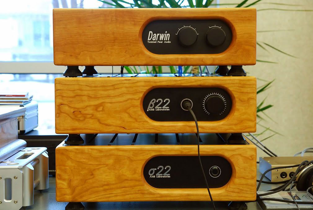
Here are a few pics of my own β22. It's a four channel, with dual σ22s in a separate enclosure. There were many hands involved with this project...luvdunhill, N_Maher & fierce_freak. The Top unit is a fully balanced TPA Darwin source selector with six balanced inputs, two balanced outputs and a balanced loop out. The cases were built by me, and are figured Black Cherry w/a five coat, modified Tung Oil finish.

dfw8_hc_04.jpg


beta22%20002.jpg


beta22%20001.jpg


beta22%20003.jpg
 
Mar 28, 2010 at 7:02 PM Post #2,625 of 3,218
Thanks! Those are amazing. I like how everything matches perfectly.

Quote:

Originally Posted by swt61 /img/forum/go_quote.gif
Very nice quattro98!

Here are a few pics of my own β22. It's a four channel, with dual σ22s in a separate enclosure. There were many hands involved with this project...luvdunhill, N_Maher & fierce_freak. The Top unit is a fully balanced TPA Darwin source selector with six balanced inputs, two balanced outputs and a balanced loop out. The cases were built by me, and are figured Black Cherry w/a five coat, modified Tung Oil finish.


Users who are viewing this thread

Back
Top