Roll Call: Who's building, built, or thinking of building a beta22?
Jan 18, 2010 at 1:03 AM Post #2,191 of 3,218
my rec, fwiw, replace the .47ohm R's as a matter of course if you replace the mosfets. I've had to, many times myself. sometimes the resistor LOOKED ok but when I replaced it things went back to working again. on the power supply, as well!

I keep a spare bunch of the .47's and also the mosfets. I've also learned to solder wire wrap wire to test points (powered down!) and avoid probes in live circuits. that always screwed me over and so I went with temp tack-on wires to do test point measurements. then power down, unsolder test wire and move to next. not elegant but I can't 'manage' probes with 100% accuracy, either
wink.gif


oh, and in terms of parts to order: don't order extra crd's unless that's your last option. they're pricey and they tend not to blow (so I'm told).

order extra transistors (they are not too expensive) and I have not had to order extras of the matched quads; only the transistors that are 'near' the final mosfets are the ones that I've had go bad on me.

clean the board well (alcohol and canned air duster) and that mostly helps you SEE if there are other zapped areas that need to be cleaned up, as shorts.
 
Jan 18, 2010 at 2:00 AM Post #2,193 of 3,218
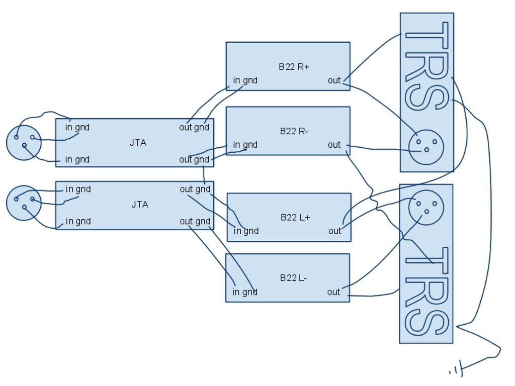
Argh! Ok, second beta question for the day. This is on my balanced rig which I've finally gotten a chance to work on. It's 4 channel with a Twisted Pear joshua tree attenuator.

The XLR jacks are wired to the two JT boards. +/- of right XLR to one board, +/- of left XLR to the other board. Of course, the corresponding outputs feed the beta boards. The beta outputs are wired to combination XLR/TRS jacks. So, the left jack has pins 2 and 3 wired to the left 2 boards AND ring from the left + board, tip from the right + board, and is grounded to the PSU. And the right jack pins 2 and 3 wired to the right 2 boards AND ring from the left - board, tip from the right - board, and is grounded to the PSU. Does that make sense?

While listening with my balanced headphones, I get one channel coming in nicely... although at less volume than I would have expected (might be just that I need more gain.) When listening with single ended headphones, I get that same channel coming in through my left and right ears from both combo jacks.

I switched the source from left to right (Buffalo 32S verified to be working correctly) and the same thing happens except it's the other channel coming in in mono.

Any ideas on what might be wrong? It feels like I have confounding results... like I should only have one side coming in when connected single ended. I reflowed all the joints on the attenuator board feeding the side that doesn't come through when listening balanced. Now I'm not sure what to check... maybe I'll measure the resistance at the in and out terminals of the JT boards to make sure they're both working correctly?
 
Jan 18, 2010 at 2:20 AM Post #2,194 of 3,218
A couple questions. I am trying to choose LEDs for my beta build. I am using amber, in the 592 nm range. I found this one: HLMP-EL35-TW0DD at Newark. Does a T-1 3/4 size bulb have lead spacing of .2 inches?

The bulb is rated at 7200 mcd, which is very bright, but will it be bright enough running at 7ma?

Last, where should I connect the LED wires for my bulgin power switch if I am using the board LED slot already? I plan on using zener diodes to drop the voltage down to 12V, but where is the best place to attach the wires?
 
Jan 18, 2010 at 4:38 AM Post #2,196 of 3,218
I'm working down a list of boards that have destructed from the single ended jack shorting. I have one board that's being particularly stubborn. All four MOSFETs were bad, as well as R32 (and maybe R28, I don't remember but I replaced it). R29 and R33 were fine. After replacing all the MOSFETs, the PSU comes up and I get +-30V rails. However, I cannot get any current through the output stage. Input stage is fine (remember, this was a working board before).

So, I was looking for a list of operating points for the b22, but I cannot seem to find it. I've taken a few measurements I'd like to compare (voltages are measured across the given device and no polarity is given):

1.5V R28
1.07V R29
0V R32
0V R33
3.2V R23
3.35V R24
50mV R25
48mV R26
1.12V D12
2.33V D11
3.9V R14
3.77V R15

There were a few traces that had to be repaired, so don't assume the board is perfect. I did double check these things, but you know, I could have missed something. Also, remember this was a previously working board. Nothing is just jumping out at me (maybe Q18?) :/

Thanks!
 
Jan 18, 2010 at 5:19 AM Post #2,199 of 3,218
oneplustwo, how about a diagram showing how everything is connected?
tintin47, you can tap the LED power from the σ22 V+ and V- output terminals, and solder the zeners inline (and shrink wrapped) to the Bulgin switch LED terminals.
 
Jan 18, 2010 at 5:21 AM Post #2,200 of 3,218
Hi,

Thanks for the advice, I replaced Q25 and the board passed the initial setup checks
icon10.gif


Snap on the screeching in three channel configuration, with apple earbuds and the volume turned down, trying with other headphones I don't get screeching.

Could the amp screeching be oscillation, and would low impedance buds be more susceptible to screeching/oscillation?

Final note: Very impressed with the B22, it sounds subtly smoother than the M3 I built, M3 has AD8610 op-amps. I think there's a clearer sonic distinction between the different headphones I've tried, which I guess is good indication of it's transparency.

Thanks again for the advice and to Ti for designing a great amp!
 
Jan 18, 2010 at 5:30 AM Post #2,201 of 3,218
Quote:

Originally Posted by Rooford /img/forum/go_quote.gif
Hi,

Thanks for the advice, I replaced Q25 and the board passed the initial setup checks
icon10.gif


Snap on the screeching in three channel configuration, with apple earbuds and the volume turned down, trying with other headphones I don't get screeching.

Could the amp screeching be oscillation, and would low impedance buds be more susceptible to screeching/oscillation?

Final note: Very impressed with the B22, it sounds subtly smoother than the M3 I built, M3 has AD8610 op-amps. I think there's a clearer sonic distinction between the different headphones I've tried, which I guess is good indication of it's transparency.

Thanks again for the advice and to Ti for designing a great amp!


i don't think the B22 would oscillate with HPs as long as your DC offset is 0. with speakers, you may need a Zobel on the speaker outs.
 
Jan 18, 2010 at 6:07 AM Post #2,203 of 3,218
For question #1: Could be oscillation... I was using my cheapo ear buds actually. I can try my grados although they're low impedance as well. Not sure what else it would be (other than the stepped attenuator) if the PSU and all three boards test out correctly.

For question #2 (the balanced rig), here's a sketch of the wiring. I tied the two JTA boards' grounds together... not sure if that matters or not. (Note TRS are three separate lugs on the combo jack.)
4284324338_fcdc5374bc_b.jpg
 
Jan 18, 2010 at 6:30 AM Post #2,204 of 3,218
One mistake I see is that you have the right channel output wired to the Tip and left channel to the Ring. That's backwards, but should only result in a reversal of left and right channels, not the symptoms you describe. I hope the picture reflects how you actually wired everything up accurately. You should double check.

Also, In this scheme, one of your TRS jacks will be out of phase relative to the other one. If you believe in the need for absolute phase correctness then one of them would be wrong. If not, then no biggie.

Thirdly, I hope that the Sleeve connection goes to the sigma22's G terminal directly, not riding on the G wire from the amp boards back to the PSU.
 
Jan 18, 2010 at 7:36 AM Post #2,205 of 3,218
Quote:

Originally Posted by amb /img/forum/go_quote.gif
Some headphone loads may be complex enough to require a zobel network as well. It won't hurt to put one on anyway.


Well, I tried it with the Grados and it works fine! Might be because one of the board's DC offset was only able to be reduced to 5mV and that in combination with my in ear phones (Ety's in my sig) made it oscillate?

Quote:

Originally Posted by amb /img/forum/go_quote.gif
One mistake I see is that you have the right channel output wired to the Tip and left channel to the Ring. That's backwards, but should only result in a reversal of left and right channels, not the symptoms you describe. I hope the picture reflects how you actually wired everything up accurately. You should double check.

Also, In this scheme, one of your TRS jacks will be out of phase relative to the other one. If you believe in the need for absolute phase correctness then one of them would be wrong. If not, then no biggie.


I'll check the wiring again tomorrow. It wouldn't be the first time I double/triple checked something and found a mistake on the fourth (or later) check.

For the TRS jacks, what would be the proper way to maintain phase? + from right and - from left for both combo jacks? I'll probably leave it as I'm not a stickler for phase correctness per se, but I would like to know so I can do it right the next time.

The ground does indeed go back to the PSU case and a sigma ground terminal on it's own wire. I have an 8-connector umbilical so I'm using one of the two slots not used by the 2 sigmas.
 

Users who are viewing this thread

Back
Top