Roll Call: Who's building, built, or thinking of building a beta22?
May 19, 2009 at 7:19 AM Post #827 of 3,218
Quote:

Originally Posted by Gatsu /img/forum/go_quote.gif
I figure the way Perth summers get I need it to handle as much heat as it can :p


Is a headphone/speaker design?

Quote:

Originally Posted by Gatsu /img/forum/go_quote.gif
I'll grab a couple of close up shots when I get home tonight.


Keep em coming
biggrin.gif


Quote:

Originally Posted by Gatsu /img/forum/go_quote.gif
The board in the middle is the power controller. Its a picaxe microprocessor as well as a 5V PSU (for the amp controller as well). The picaxe senses the supply rails through 4 opto-couplers and if one drops out it flashes an error code on the power switch LED.


Never heard of this, like to hear more about the pros and cons regarding this feature - never seen any on other builds.
 
May 19, 2009 at 8:16 AM Post #828 of 3,218
Quote:

Originally Posted by johnwmclean /img/forum/go_quote.gif
Is a headphone/speaker design?

Keep em coming
biggrin.gif


Never heard of this, like to hear more about the pros and cons regarding this feature - never seen any on other builds.


Primarily headphone, but I like to leave my options open
smily_headphones1.gif


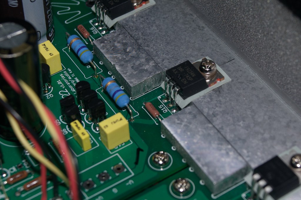
The is definitely a case of me making something more complicated than it needed to be :p

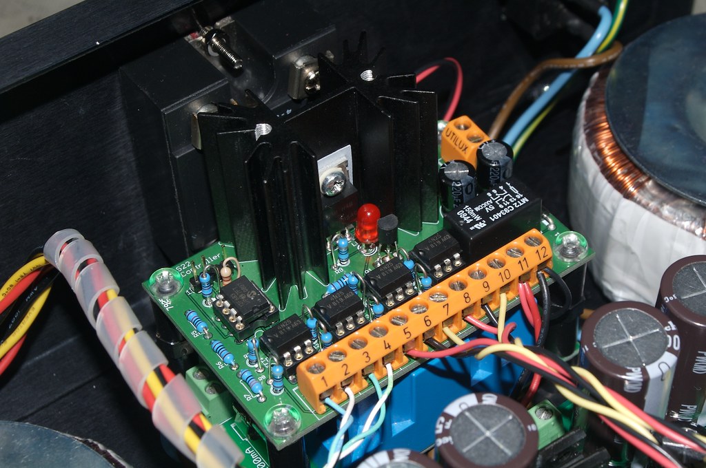
I wanted the front panel of the PSU case to just have a single button with the power indicator, however it was to be a dual PSU so I really needed to be able to show what state each PSU was in.
My original idea was to use the LED into an optocoupler and that told the microcontroller the sigma was working.

But! During the build, I messed up. One rail had 40V and the other 0V, but the LED was still lit, ok so that idea wasn't going to work the way I wanted, and it evolved into what it is now. Who says I don't learn from my mistakes :p

As you guessed yes there are pros and cons to this. The main downside is that you can't tell what the actual voltage is, just that there is voltage and its over the threshold for the optocoupler and picaxe logic to trigger. You could fine tune the threshold with some experimentation however, so it would be a known value.

The Arduino rig on the breadboard is a much better way of doing this (the Arduino has 6 analog inputs while the picaxe08M has 3, the picaxe20 has 6). I can sense 6 analog lines and give accurate values, so the four voltage rails as well as temperature in each case, not to mention output to an LCD. That's getting close to information overload though :p

As it is, the power LED will flash a different code depending which sigma22 is giving problems or if both are down.

All because I just wanted a single power indicator on the front of the case :p

I was a bit hesitant about the picaxe at first but I had a little help from someone at work to get started (Thanks Egon!) and it turned out easier than I initially thought.
 
May 19, 2009 at 8:53 AM Post #829 of 3,218
^ WOW my LEDS are purely cosmetic then LOL. Thankyou so much for the info, I'm really looking forward to those pics.

If this turns out to be a purely headphone psu, you get my vote for over the top OVERKILL. Please keep us posted with your amp developments!
 
May 19, 2009 at 11:39 AM Post #830 of 3,218
As requested, a closeup of the FETS mounted on the heatsink
3544958305_e72e5a1788_b.jpg

As you can see I cut away a section of the heatsink. This helps the fins of the heatsink line up with the vents in the bottom of the case.

And also a closeup of the picaxe controller
3544958135_d6b7a993f5_b.jpg


The four six pin chips near the front are the optocouplers - one for each rail.
Behind the heatsink for the regulator you can see the solid state relay mounted to the back panel.
 
May 20, 2009 at 11:33 PM Post #832 of 3,218
Primarily the picaxe handles the power switching with some added bells and whistles.
In its simplest form it allows you to use a momentary push button to toggle the power on and off. But because of the additional inputs and logic also allows you to do some more interesting stuff.

If you didn't want to get fancy you could trim it down to just a handful of components to switch the power.

The Conrad (well I think its a Conrad - I bought them from my local Jaycar, no brand is mentioned on them) wasn't too bad to work with. It was just fiddly lining up everything at once.

Hopefully I'll get time to start casing up the amp this weekend.
 
May 21, 2009 at 6:37 AM Post #834 of 3,218
Quote:

Originally Posted by fault151 /img/forum/go_quote.gif
So it is a bit like the AMB LABS e24 board in a way. That is what i am using with my illuminated bulgin switch and power relay.

Can't wait to see your finished amp.


im in the middle of soldering my e24, myself! my bulgin switch has a red LED - what about yours?
 
May 21, 2009 at 7:44 AM Post #836 of 3,218
Quote:

Originally Posted by fault151 /img/forum/go_quote.gif
I went for the blue type as my leds on the psu and amp are also blue.

Here's my blog which i post quite a bit about my b22 build on there.


Very cool blog, any more info on that relay board by MrMajestic?
 
May 21, 2009 at 8:28 AM Post #837 of 3,218
Quote:

Originally Posted by Nebby /img/forum/go_quote.gif
Very cool blog, any more info on that relay board by MrMajestic?


In terms of trying it out i haven't had chance yet. I'll post a blog wehen i do get it hooked up.

If you need info on the actual design, PM him, im sure he will be happy to help.

He also designed another version which switches for a prer amp. I would have had that but was struggling for space in my amp.
 
May 21, 2009 at 9:02 AM Post #838 of 3,218
space is certainly at a premium in my setup - im cutting every corner imaginable to get the amp section (all 4 boards, plus attenuator) into a 310mm x 230mm 1U enclosure. should look AMAZING... should I succeed...
 
May 21, 2009 at 12:01 PM Post #839 of 3,218
Quote:

Originally Posted by El_Doug /img/forum/go_quote.gif
space is certainly at a premium in my setup - im cutting every corner imaginable to get the amp section (all 4 boards, plus attenuator) into a 310mm x 230mm 1U enclosure. should look AMAZING... should I succeed...


I hope you've accounted for ventilation. The more I work on beta22's the more I think you can never have too much.
 
May 23, 2009 at 8:37 AM Post #840 of 3,218
I have partial success with mine now. The Sigma 22 is fixed but only one of the three boards is making sound. One seems to be blown blown and the third measures properly and the LED is lit but nothing is coming out so I have to see what's going on tomorrow. Hopefully it's something simple. If not I'll be running a single board mono Beta 11
biggrin.gif
 

Users who are viewing this thread

Back
Top