Roll Call: Who's building, built, or thinking of building a beta22?
Oct 27, 2009 at 9:25 PM Post #1,936 of 3,218
Possédé, what you've linked to looks like an incandescent lamp, not LED. If so, its operating current may be highly variable depending on the filament temperature and is difficult to predict. You'd have to experiment to get an appropriate series resistance.

cfcubed, using 100pF would cut the amp's bandwidth severely. Why not just get the correct 33pF caps? I generally don't recommend putting in "temporary" substitute parts only to replace them later, because it would require desoldering and resoldering, and needlessly stressing the board pads.
 
Oct 27, 2009 at 9:41 PM Post #1,937 of 3,218
Quote:

Originally Posted by cfcubed /img/forum/go_quote.gif
Found myself short a couple 33pf for C1 with 100pfs available... Would be detrimental to use the 100pf for C1s (perhaps until a future parts order)?


When I ordered parts for iPodPJ's build, I transposed the quantities for the 33pF and 47pF parts so have some extra 33pF parts.

PM me a mailing address and I'll send you a couple.

se

nodualxlr.gif
 
Oct 27, 2009 at 10:03 PM Post #1,938 of 3,218
Quote:

Originally Posted by amb /img/forum/go_quote.gif
cfcubed, using 100pF would cut the amp's bandwidth severely. Why not just get the correct 33pF caps? I generally don't recommend putting in "temporary" substitute parts only to replace them later, because it would require desoldering and resoldering, and needlessly stressing the board pads.


Thanks - I'll not be using the 100pf. Reason was its a bit of ride (during business hours) to a place I can pick up 33pFs and, not needing any other parts ATM, doesn't warrant yet another parts order...
Quote:

Originally Posted by Koyaan I. Sqatsi /img/forum/go_quote.gif
PM me a mailing address and I'll send you a couple.


Thank you very much for the offer... But I'll make tomorrow (Wed) a "work-from-home" day & take a long lunch to get them & a few more things
wink.gif
 
Oct 27, 2009 at 10:07 PM Post #1,939 of 3,218
Quote:

Originally Posted by cfcubed /img/forum/go_quote.gif
Thank you very much for the offer... But I'll make tomorrow (Wed) a "work-from-home" day & take a long lunch to get them & a few more things
wink.gif


Okie doke.

se

nodualxlr.gif
 
Oct 27, 2009 at 11:48 PM Post #1,940 of 3,218
Oct 28, 2009 at 12:10 AM Post #1,942 of 3,218
Quote:

Originally Posted by rhester /img/forum/go_quote.gif
Is that your wood work or somebody else? Looks very well done>


thanks. my woodwork, done with a router table and chop box - 4 coats of tung-oil. the top and back aluminum plates were sanded with 320 grit and several coats of clear spray paint. i then sanded them down with 0000 steel wool to get an anodized look.
 
Nov 1, 2009 at 3:19 PM Post #1,943 of 3,218
Quote:

Originally Posted by amb /img/forum/go_quote.gif
Possédé, what you've linked to looks like an incandescent lamp, not LED. If so, its operating current may be highly variable depending on the filament temperature and is difficult to predict. You'd have to experiment to get an appropriate series resistance.


Cheers, I never realised that it was an incandescent and not an LED. I found an alternative LED indicator.

Now, what I am about to ask may come across as silly... But is there a way of securely fixing the boards and transformer to the case without screws being visible from the bottom. I just don't like the idea of having a big silver M5 screw head sticking out from underneath the black case (And lots of M3 screws). I was thinking of cutting a sheet of aluminium that would fit into the side grooves of the Galaxy Maggiorato, which the boards and transformers can be attached to.

Another question is, as my case is anodised aluminium (which to the best of my knowledge is a non-conductor of electric current), how do I go about earthing my case. Would all I need to do is attach a wire from the earth terminal to a part of my case which is not anodised? For instance, if I cut a hole in the back of my case, put a screw through it, and wound the earth wire around that screw and tightened it with a nut.

Any input would be appreciated.
 
Nov 1, 2009 at 3:49 PM Post #1,944 of 3,218
Quote:

Originally Posted by Possédé /img/forum/go_quote.gif
I found an alternative LED indicator.


That things is going to be mighty bright at 7000mCD. Also, looks like it has either an internal resistor or current regulator, so you need to power it with a raw 12-28V. See this thread about using a zener diode to drop the power supply voltage to within those limits.

Quote:

Now, what I am about to ask may come across as silly... But is there a way of securely fixing the boards and transformer to the case without screws being visible from the bottom.


Either you conceal them with another panel, or use a really thick bottom plate and have some threaded blind holes (that doesn't go all the way through to the bottom). But why? It's the bottom and you're not going to look at it when it's sitting down...

Quote:

Another question is, as my case is anodised aluminium (which to the best of my knowledge is a non-conductor of electric current), how do I go about earthing my case. Would all I need to do is attach a wire from the earth terminal to a part of my case which is not anodised? For instance, if I cut a hole in the back of my case, put a screw through it, and wound the earth wire around that screw and tightened it with a nut.


Only the anodized surface is non-conductive. The aluminum itself is still conductive. If the panels are fixed to each other with screws, then the screw threads should be able to electrically couple all the panels. For anything that needs to connect to the chassis (i.e., the IEC AC ground), you can drill a hole on the bottom plate, crimp or solder the wire to a ring terminal, and secure it to the plate with a short machine screw, serrated lock washer and nut. The lock washer should "bite" through the anodizing and make electrical contact. If not, you can scrape away some of the anodizing around the hole.

 
Nov 1, 2009 at 5:17 PM Post #1,945 of 3,218
amb - Can you answer the PM I sent you, please?

Does anyone have a graph shows the Beta22's frequency response?
 
Nov 1, 2009 at 5:23 PM Post #1,946 of 3,218
Quote:

Originally Posted by pila405 /img/forum/go_quote.gif
Does anyone have a graph shows the Beta22's frequency response?


There is a graph in the RMAA test results found in the "Specifications" section of the β22 website. However, that graph does not represent the complete bandwidth of the amp, because it is limited by the computer sound card used for measurement. The actual graph is a ruler flat line from 0Hz to well above audio range, and rolls off to -3dB at 2.5MHz.
 
Nov 1, 2009 at 7:04 PM Post #1,947 of 3,218
Quote:

Originally Posted by pila405 /img/forum/go_quote.gif
amb - Can you answer the PM I sent you, please?

Does anyone have a graph shows the Beta22's frequency response?


You're a demanding little ...... person...... aren't you?
 
Nov 1, 2009 at 7:06 PM Post #1,948 of 3,218
Quote:

Originally Posted by amb /img/forum/go_quote.gif
There is a graph in the RMAA test results found in the "Specifications" section of the β22 website. However, that graph does not represent the complete bandwidth of the amp, because it is limited by the computer sound card used for measurement. The actual graph is a ruler flat line from 0Hz to well above audio range, and rolls off to -3dB at 2.5MHz.


WOW! Realy?! It sounds amazing!
o2smile.gif
 
Nov 2, 2009 at 3:06 PM Post #1,949 of 3,218
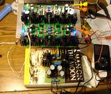
BTW, got those 33pf C1s & my boards seem GTG. All measurements & temps are dead on (now
redface.gif
anyway). Built from Jeff's (glassjaraudio) kits. Once again, have to say he's providing a great service to this community. Only one tiny part error (2 x 100pf instead of 33pf) & I'm replacing one blue LED, no biggie considering the pile of parts.

Of course PCB design, layout, etc. are nicely symmetrical & generally outstanding - sorry Ti if we are overloading you w/kudos lately but they are deserved.

Initially, only 1 board came up nicely, the other's voltages were off (e.g. offset would not stabilize below 100mv). Although thought I was very methodical in the parallel populating of the boards, on 2nd visual inspection there was a single un-soldered joint.


A few things drove my choice to give a non-σ22 PS a try, e.g. size of case on-hand, wanting 2-box build advantages w/o 2 boxes, co$t & having 2 matched 24VAC .833A wallwarts. So the PS is a simple non-tracking 7824/7924 affair. Perhaps could have gone w/minimalist tracking bit from Fig 16 of Fairchild DS. Remains to be seen how this thing will perform compared to one w/a "proper" PS or to a proper M³ which would come in somewhat below the cost of this. Counting on β22's high PSRR & keeping transformers out of the case.

If things continue to go well I'll bring this to Nov 14th NYC meet. We'll see.
 
Nov 2, 2009 at 3:24 PM Post #1,950 of 3,218
I'm trying to adjust the VR2, while getting the measurements on the R34, supposedly in the range of 55mV to 75mV. I can't seem to pin down an exact reading on the multimeter. The number jumps around from roughly 68mV to 74mV. Is the variation supposed to be that great?

This is at amp operating temperature, and following all the guidelines from the amb website.

I've measured the AC line, and AC voltage is pretty stable at 224-223 volts.
DC power from the S22 is also pretty stable at 29.8 to 29.9 volts.
 

Users who are viewing this thread

Back
Top