Resampling explained
Dec 13, 2012 at 12:21 PM Post #16 of 49
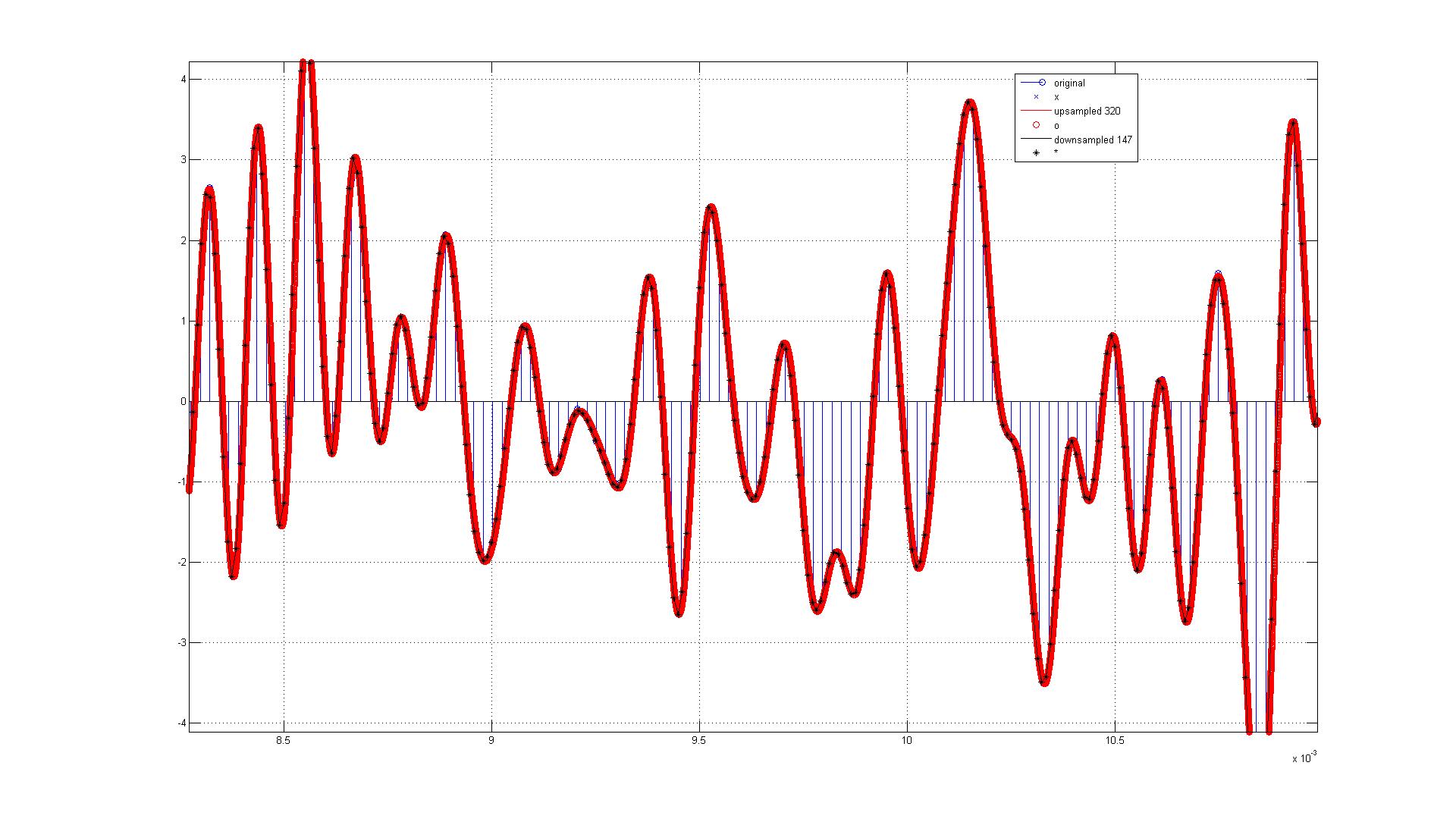
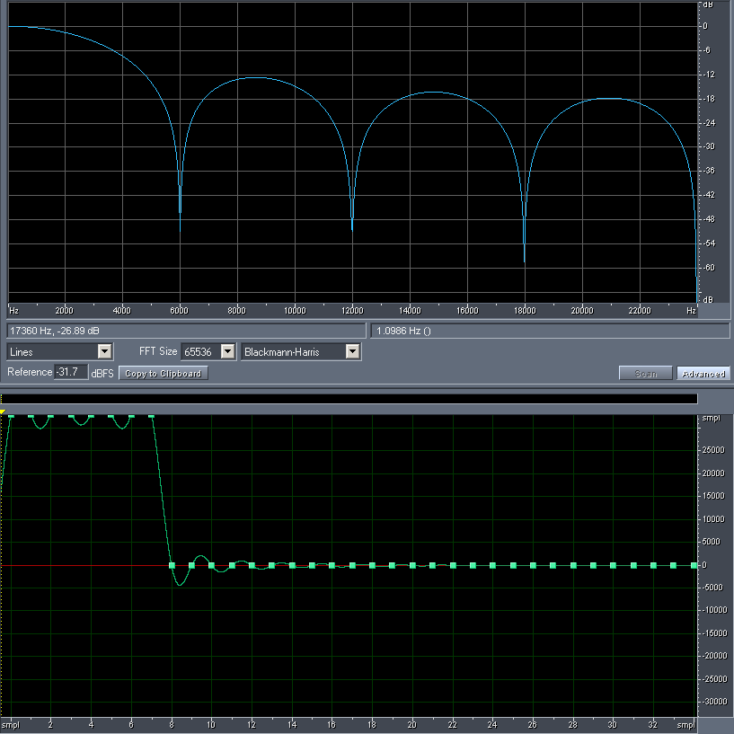
Sound Forge probably used interpolation to eliminate the ultrasonic images, as one would expect from a high quality resampler, that is why there are no zero samples between the original samples.
 
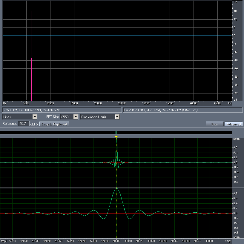
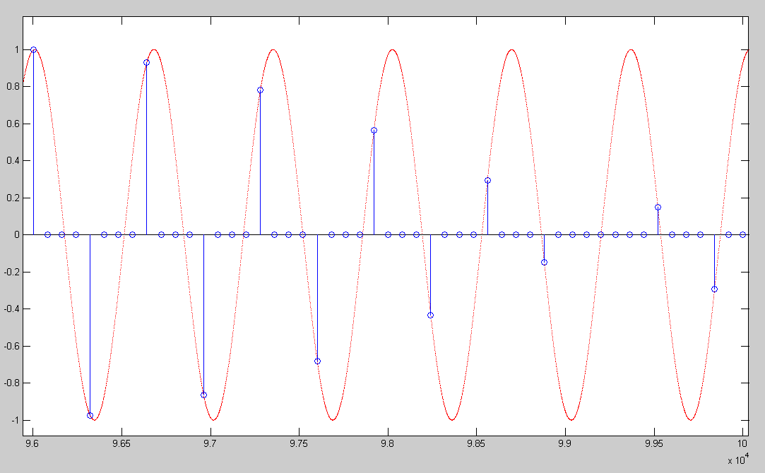
Inserting zeros does reduce the RMS level, but the interpolation filter should take that into account, and amplify the signal to the correct level.

 
Dec 13, 2012 at 12:21 PM Post #17 of 49
Quote:
Originally Posted by EthanWiner /img/forum/go_quote.gif
 
Edit: I understand that the zero-level samples don't appear in the data because they're higher in frequency than audio and are filtered out. So the better question is, why doesn't inserting zeroes reduce the level to half?

Exactly, you cannot see the zeros because they are filtered out in the resampling process. All of the details described in the #1 post are hidden from the user in an audio editor, all you see is the filtered result.
 
Yes, adding one zero per sample exactly halves the level. This is also corrected by the lowpass filter. How? By increasing the DC gain of the lowpass from 0 dB (1x) to +6.02 dB (2x).
This is just another optimization, because you could also multiply each original sample by 2x before filtering.
wink.gif

 
edit: stv014 was faster, again.
 
Dec 13, 2012 at 12:29 PM Post #18 of 49
Actually, a sin(x * ℼ / L) / (x * ℼ / L) impulse response (where x is the time in samples) already has a DC gain of L. The image below shows this with L=8:
 

Other, lower quality interpolations can also be thought of as filters applied to the initial "(L - 1) zeros inserted" upsampled signal, for example a simple sample duplication has an impulse response of L 1.0 samples, while linear interpolation is equivalent to a triangle impulse response (rising from 0 to 1.0 in L samples, and then back to zero in L samples). In all cases, the DC gain is L.
 
Dec 13, 2012 at 1:59 PM Post #19 of 49
Yeah, a matter of how you define stuff.
 
The normalized sinc function:
sinc(x) = sin(pi*x) / (pi * x) ... has the value 1 where x = 0
 
For a lowpass filter with normalized frequency (0.5 = Nyquist frequency) I use this:
 
filter(x) = sin(2*pi*fc*x) / (2*pi*fc*x) ... where fc is the cutoff frequency. The value is still 1 where x = 0.
 
The 2*fc within the sin() sets the cutoff frequency, and the other 2*fc in the denominator scales the values accordingly.
 
Using fc = 0.25 is equivalent with your /L where L = 2.
 
Dec 13, 2012 at 5:30 PM Post #20 of 49
Quote:
That said, mathematically and practically, there is more than one way to do the same thing. By changing the filter, you can switch the order of filtering and downsampling or upsampling.

 
This is correct, but may deserve a little clarification. One can swap the decimation/interpolation filtering with the downsampling/upsampling operation respectively when using efficient downconvert/upconvert multirate structures. This is a bit advanced and can lead to confusion though.
 
However, one should not swap the upconvert operation with the downconvert operation as this can result in the original signal going bye-bye (in xnor's example this means the signal BW would be reduced to 1/147th of its former self.)
 
Dec 13, 2012 at 5:34 PM Post #21 of 49
Whoops, should've written that more clearly. Swap filtering and downsampling, or filtering and upsampling, in some sense. May or may not be worth the trouble. NOT upsampling with downsampling, as you say. :eek:

Or with less caution, multiply factor of L whenever. Just make sure you're not clipping anything and the right amplitude comes out in the end. When it happens? Up to you.
 
Dec 13, 2012 at 5:53 PM Post #22 of 49
Quote:
Whoops, should've written that more clearly. Swap filtering and downsampling, or filtering and upsampling, in some sense. May or may not be worth the trouble. NOT upsampling upconversion with downsampling downconversion, as you say.
eek.gif

Or with less caution, multiply factor of L whenever. Just make sure you're not clipping anything and the right amplitude comes out in the end. When it happens? Up to you.

 
LOL! You wrote it correctly before... Confusing is in it. To be honest, I always mix up terms myself.
 
Here is another resampling example
biggrin.gif
:
 

BTW, the legends on the above are wrong. It should say original, upconverted, and downconverted
blink.gif

 
Dec 14, 2012 at 12:28 PM Post #23 of 49
Quote:
Originally Posted by xnor /img/forum/go_quote.gif
Yes, adding one zero per sample exactly halves the level. This is also corrected by the lowpass filter. How? By increasing the DC gain of the lowpass from 0 dB (1x) to +6.02 dB (2x).

Okay, got it, thanks. And because this is all done in the digital domain, adding 6.02 dB doesn't increase the noise, it just puts the signal back to the right level.
 
I still don't understand why this is better than simply repeating each sample. I'm not a math guy, so if the explanation requires math, don't bother.
blink.gif

 
--Ethan
 
Dec 14, 2012 at 12:51 PM Post #24 of 49
I hope these graphs will clear things up.
 
 
First, a 44.1 kHz test signal with HF roll-off to show what's going on more clearly:


The same test signal but zero-stuffed to 88.2 kHz. Notice how the spectrum is mirrored around 22.05 kHz, but the spectrum of the original signal did NOT change. If we filter out the stuff above 22.05 kHz with a lowpass filter we will get the original signal at twice the sampling rate:


Now we repeat each sample instead of zero-stuffing. Notice the additional roll-off and zero at 44.1 kHz (= a comb filter). If we filter out stuff above 22.05 kHz we still would have to counter-act the additional roll-off:

 
Also, as I said before you can use the zeros to optimize the resampling process, but if you repeat samples you have to include them in the filtering process.
 
Dec 14, 2012 at 4:57 PM Post #25 of 49
Repeating each sample vs. zero insertion is not better or worse, it just requires a possibly more involved filter to interpolate between samples (so in that sense I guess it's worse.)
 
If one just adds zeros in between samples, the interpolation low pass filter requirement is to be as flat as possible in the pass band, and reject as much as possible in the stop band. This results in optimal interpolation between the samples for a band limited signal.
 
There are a few well known and readily available filters than can do this. A windowed FIR Sinc filter would certainly do the trick and is sort of optimal, but there are other options like the IIR Butterworth, Chevyshev, and so forth that might do the trick depending on requirements (trade offs in filter size, band rejection, phase distortion, pass band flatness, linear phase vs minimum phase, cut-off steepness ...).
 
If using a sample and hold (S/H) technique then the interpolation low pass filter needs to be off from flat in the pass band. A flat (in pass band) low pass filter will do a poor job at smoothing the resulting stair case approximation from the S/H operation. Some form of compensation is required from the filter. The S/H technique with no compensation may be more common in certain DAC applications (probably excludes hi-fi audio applications though.)
 
Dec 16, 2012 at 12:39 PM Post #27 of 49
Quote:
Originally Posted by EthanWiner /img/forum/go_quote.gif
 
I still don't understand why repeating samples creates a comb filter and skews the response below 20 KHz, but I believe you.

 
An impulse response consisting of a +1.0 sample, then (N - 1) * zero samples, and finally a -1.0 sample is a comb filter that has zero magnitude at Fs * k / N Hz, and 2.0 (+6.02 dB) at Fs * (k + 0.5) / N Hz, where k is any integer. Now a "block" impulse response of N consecutive 1.0 samples is the result of integrating (-6 dB / octave over the entire frequency range) the above comb filter. That cancels out the notch at DC, and creates the overall high frequency roll-off of the response, but other than that it is still a comb filter. This is shown below with N=8. Sample duplication is like zero insertion convolved with an impulse response of L 1 samples.


Note that the frequency response of the filter is in fact based on the sinc function, the sin(x) comes from the comb filter, and the division by x from the integration. However, integration does not in fact have an accurate -6 dB / octave response as the Nyquist frequency is approached, since it is the inverse of differentiation (an impulse response of 1, -1), which is a special case of the comb filter (N=1) and really has a sin(⍵ / 2) * 2 magnitude response.
 
Dec 16, 2012 at 2:36 PM Post #28 of 49
A very practical answer: imagine the highest possible frequency with the sample values +1, -1, +1, -1, +1 and so on.
 
If we double the sampling rate and don't insert 0 between +1 and -1 but repeat each sample (+1, +1, -1, -1 ...) we've effectively killed the new highest possible frequency - that's our null in the FR.
And since this "filter" is very short there cannot be an abrupt roll-off, instead it has to be smooth and gradual.
 
After all, a perfect brickwall lowpass filter also rings infinitely long in the time domain.
 
Dec 16, 2012 at 2:54 PM Post #29 of 49
Quote:
Originally Posted by xnor /img/forum/go_quote.gif
 
If we double the sampling rate and don't insert 0 between +1 and -1 but repeat each sample (+1, +1, -1, -1 ...) we've effectively killed the new highest possible frequency - that's our null in the FR.

 
Actually, in this example the result is a Fs/4 tone regardless of whether zeros are inserted or samples are duplicated. The difference is that the duplication method will output 3 dB higher RMS amplitude, and the phase delayed by 45 degrees. Why not 6 dB ? Because the filter has an attenuation of 3 dB at that frequency relative to DC (see the graph above at 6 kHz).
 
Dec 16, 2012 at 3:06 PM Post #30 of 49
Quote:
 
Actually, in this example the result is a Fs/4 tone regardless of whether zeros are inserted or samples are duplicated. The difference is that the duplication method will output 3 dB higher RMS amplitude, and the phase delayed by 45 degrees. Why not 6 dB ? Because the filter has an attenuation of 3 dB at that frequency relative to DC (see the graph above at 6 kHz).

Yeah that's why I wrote "we've effectively killed the new highest possible frequency". If we went from 44.1 kHz to 88.2 kHz the null is at 44.1 kHz and the 22.05 kHz tone of course stays a 22.05 kHz tone.
 
Yeah, there's half a sample group delay, or 45° at 22.05 kHz and a smooth roll-off (+6 dB at DC, +3 dB at 22.05 kHz) but all this might confuse Ethan more than help. :D
 
 
edit: 3 dB roll-off maybe doesn't seem much but if we think in terms of specs like "20 Hz to 20 kHz +- 0.1 dB" it is. And it gets worse as we insert more repeating samples, e.g. we get about -3 dB at 20 kHz with L = 4.
 

Users who are viewing this thread

Back
Top