

drtechno
100+ Head-Fier
- Joined
- Nov 14, 2016
- Posts
- 148
- Likes
- 25
What is wrong with the Fikus design of tis solution?
I don't know who Fikus is.
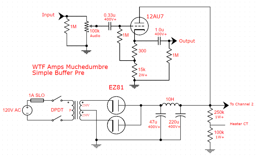
But looking at the schematic above it doesn't really show where he is getting the plate supply from. If this person is tapping off the primary of the transformer, then this would be an very unsafe unit indeed.
I don't know who Fikus is.
But looking at the schematic above it doesn't really show where he is getting the plate supply from. If this person is tapping off the primary of the transformer, then this would be an very unsafe unit indeed.
