Request for help - Looking for someone to help me understand the lampizator circuit diagram
Aug 10, 2008 at 4:47 PM Thread Starter Post #1 of 23

ianp

100+ Head-Fier
Joined
Feb 24, 2008
Posts
122
Likes
0
Hello All,

I have been tweaking the ZERO DAC and have been reporting back into review thread.

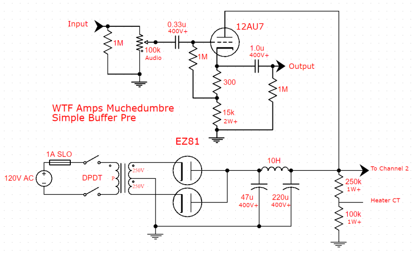
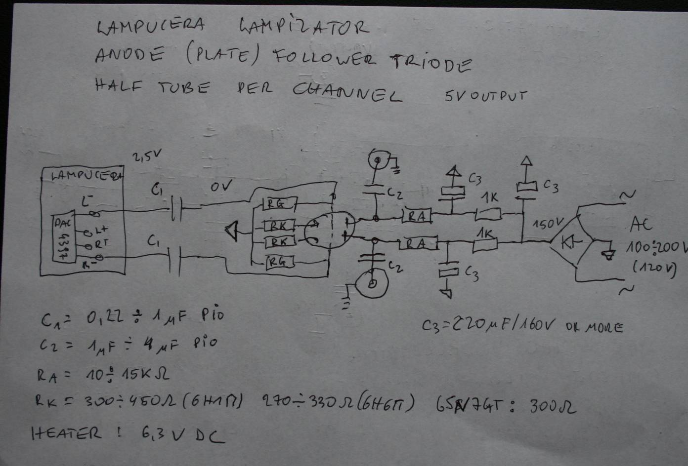
I am now considering adding a 6N6P tube to the DAC as a further (and some might say drastic) mod. The modification is detailed on this page and I am looking for some assistance in translating the provided circuit diagram - see below - into a set of instructions that I and others can easily follow.

IMG_5144.jpg


I have started an embryonic wiki page that tries to bring everything together in a set of simple and concise instructions. However, my knowledge of electrical circuitry is rudimentary at best and my knowledge pertaining to tubes is non-existant. Thus, I am looking for help in validating what I have put together and then taking it to the next level of fleshing out the implementation steps.

If anyone is willing to help out as a backgorund task it would be greatly appreciated and please contact me via PM.

Thanks
 
Aug 14, 2008 at 6:06 PM Post #2 of 23
This looks very interesting. I am rather certain I would be of little assistance to you, but I hope some folks do help you as I would like to benefit from it
smily_headphones1.gif
 
Aug 14, 2008 at 11:06 PM Post #3 of 23
There is a stack of information on his site, but it's not all easy to find. I found the page called quick_lampizator helpful, as is the lampucera_boxed page. I'll find and post the links tonight (if they haven't been by that time).

I think I have a reasonable handle on waht he is saying, but it will be useful (to me) to watch further comments by people far more knowledgeable than I am.
 
Aug 15, 2008 at 9:58 AM Post #4 of 23
Here is the quick_lampizator page.

This one shows a slightly different circuit. The primary difference between the two is that this shows the connections for DC heaters rather than the AC heaters in the quick guide.

These pages both show his cathode follower circuit and not his anode follower circuit you are asking about. Hopefully these will serve to help rather than confuse.
 
Mar 23, 2009 at 5:53 AM Post #5 of 23
I've revived this thread to ask if anyone has successfully implemented Lampizator's mod which adds a vacuum tube output stage to the Zero Dac?


The pictures and his comments are from Lampiztor's website: Lampizator's ZERODAC

IMG_5523.jpg

http://www.lampizator.eu/LAMPIZATOR/...C/IMG_5524.jpg

Ze post-lampization sound


Which is the most common language in the world ???
Chinese ?
Not ...
Think again ...
Spanish ?
nope ...
Yes !

it is bad English.

The same principle applies to CD playback. The most common system is good DAC chip and lousy analogue output stage.
In Zero dac it is no different. Excellent chip is followed by bad output stage. Not nearly as bad as the really bad ones, but nevertheless killing all the subtle nuances.
With lampizator which takes the signal directly from DAC legs - the sound opens up incredibly. I rank it really very high. It is warm, full, extended, wide, deep, natural, powerful and musical. I would say it is equally good as CS4397 which is a hell of recommendation !
It is less detailed than CS but more warm and musical. The differences are super small. Anyway, I suggest that this is an extremely safe buy, worth the effort of lampization and it beats 90 % of other lampized players. It is about equal to B-B PCM1794 . Personally I liked it very much. Particularly the bass is surprisingly good. All in all - for a mere U Out DAC this is spectacular.
It gets my seal of approval and it belongs in upper part of class one of players. Almost class zero really.
 
Mar 24, 2009 at 9:18 PM Post #6 of 23
I too would love to know these results and comparisons! If it is as good as Lampizator dude says it is then this is indeed a bargain.

Anyone?
 
Mar 24, 2009 at 9:58 PM Post #8 of 23
I'd be willing to pay someone to do this mod on my zero and keep it for comparisons etc. for a little while. I just don't have solder skills! Would need to be UK though. I especially like this pic:
 
Mar 24, 2009 at 10:36 PM Post #9 of 23
I would love to see the internals on that, must be a tight fit for either a cap multilier or a small transformer....
 
Apr 4, 2009 at 3:52 AM Post #10 of 23
Quote:

Originally Posted by tinseljim /img/forum/go_quote.gif
I'd be willing to pay someone to do this mod on my zero and keep it for comparisons etc. for a little while. I just don't have solder skills! Would need to be UK though. I especially like this pic:


I don't think anyone at Head-Fi is capable of duplicating the Lampizator's Zero Dac mod. I wonder if anyone that has jumped on the HDAM bandwagon (e.g. Pete's Frankenzero) is willing to challenge the Lampizator on who has the best sounding Zero Dac.

I have a feeling that the Lampizator has the best sounding Zero Dac.
 
Apr 4, 2009 at 5:41 AM Post #11 of 23
Quote:

Originally Posted by ianp /img/forum/go_quote.gif
If anyone is willing to help out as a backgorund task


It is just a grounded cathode circuit, and not a well designed or implemented one at that.

Quote:

Originally Posted by tinseljim /img/forum/go_quote.gif
If it is as good as Lampizator dude says it is then this is indeed a bargain.


It's doubtful. There is much wrong with that circuit.

Quote:

Originally Posted by adamus /img/forum/go_quote.gif
surely the gain of this is going to make it a very hot source?


Also doubtful. He is just taking the signal off the Iout, and only half of what is available thus ignoring the balanced chip. mu on the tube is low, and the degenerative cathode feedback will drop it lower still.

Quote:

Originally Posted by Haoting /img/forum/go_quote.gif
I don't think anyone at Head-Fi is capable of duplicating the Lampizator's Zero Dac mod..


Speak for yourself. I think the issue is that anyone capable of doing it knows that the DAC itself is poorly implemented and not worth the effort, and that the mod itself is poorly conceived. It really isn't even a case of saying that any particular part of it is done badly as every part is. There is nothing about it done right, from the cap input, to the type of bias, to the tube's load, to the power supply, to the lousy wiring job. It is all wrong.

For a better circuit that can be tacked onto the DAC chip, see here: Active output Of course at that point, you might as well get yourself a better DAC, too.
 
Nov 17, 2016 at 11:45 AM Post #14 of 23
I'm here (i'm new to the site btw) yes there is better ways to do this.
 
I don't have time now to post a schematic. but the best way is to use the input section of the tube as part of the last stage of the dac instead of it being tied to it as the next stage. grounded cathode or not in topology.
 
The reason behind that is the filter becomes an active part of the DAC and slew rate performance increases because of the signal potential.
 
Nov 17, 2016 at 4:04 PM Post #15 of 23
  I'm here (i'm new to the site btw) yes there is better ways to do this.
 
I don't have time now to post a schematic. but the best way is to use the input section of the tube as part of the last stage of the dac instead of it being tied to it as the next stage. grounded cathode or not in topology.
 
The reason behind that is the filter becomes an active part of the DAC and slew rate performance increases because of the signal potential.

Thank you! As soon you can, please, post the schematic! I would like make the simple approach. I'm not a a technician but I can understand something and I will work together my technician.
 
What is wrong with the Fikus design of tis solution?
 

Users who are viewing this thread

Back
Top