PPA v2 construction discussion
Aug 3, 2007 at 2:25 AM Post #256 of 1,084
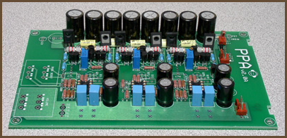
Finally matched my Output tranies, got MJE253 exactly matched at HFE 150, got MJE243 matched at HFE 116+/-1%(actually 117 for both L and R, 115 for G).

As I can see it is almost mission impossible to have same HFE for both MJE253bundle and MJE243 bundle. Same thing happened to my 2N5087 bundle and 2N5088 bundle.

Hope the above HFE difference is not big deal, one thing I can say to myself.... the BJT match work is done, now my soldering iron is smoking.....
very_evil_smiley.gif
 
Aug 13, 2007 at 2:17 AM Post #257 of 1,084
I bought RK27 pots from Tangent, so I know they must be Genuine. Then I ran some testing.

I used Tangents's scale (http://tangentsoft.net/audio/misc/atten-meas-scale.pdf) and here are the results for my two RK27 pots' resistance between pin 2 and pin 3 for each channel respectively.

Pot #1.
Shaft Position(Degree): 0 60 150 240 300
Channel L Resistance: 46.7K 46.2K 40.7K 18.2K 0
Channel R Resistance: 46.2K 45.6K 40.2K 18.2K 0


Pot #2.
Degree: 0 60 150 240 300
Channel L Resistance: 46.8K 46.4K 41K 18.8K 0
Channel R Resistance: 46.8K 46.3K 40.6K 18.5K 0

From above results, we can see the worst case of the channel mismatch can be up to 600 Ohm when resistance is around 45.6K, this looks not too good. I believe this is why some folks prefer the Stepped Attenuator.
 
Aug 13, 2007 at 5:53 AM Post #258 of 1,084
In my tests, I measured voltage, not resistance, on purpose. Resistance tells you almost nothing by itself. What matters is the voltage division factor, which you test by comparing the voltage across the pot with the voltage at the wiper. I could do the math to convert your numbers to the voltage numbers, but it's much easier to tell you to go re-do your test using the correct methodology.
tongue.gif
 
Aug 13, 2007 at 6:47 AM Post #259 of 1,084
^ What tangent said.

If you then convert the voltage divider ratio differences into dB, you'll then get something much more meaningful. 600 ohms might seem like "a lot" of difference between the two sides of a 50K pot, but if you do the math, you'll find that the pot actually tracks very well (within a fraction of a dB) over much of its range, and then deviating to no more than 2dB at the lowest volume setting just before it goes mute.
 
Aug 16, 2007 at 1:54 AM Post #261 of 1,084
few questions on my build i just put together:

the measurement for the voltage across the power resistors fluctuates +/- 1mV. is this normal, or should i be concerned?

also, i'm getting a loud buzzing sound, but i haven't put in the pot yet. would adding the pot make the buzz go away? (i was curious to see if there would be any sound, i havent had time to get the pot on yet)

last thing, i'm also getting a really loud pop when i turn the amp on (i can see the drivers of my ksc75 physically moving and hear it clearly when they're sitting on my desk), will this also be gone when i put the pot on, or is there something else?

so far i've done the heat test (transistors get hot, opamps get warm) and i've measured my dc offset for both channels (it was ~1.2mV and 1.4mV, nothing to be concerned about). i also measured from ground to the v+ and v- pins of the L and R opamps (opa637 btw, gain is set to 6.somethinghigh, i was originally shooting for 7, which would use r4 = 6.4 ohms, but i could only find 6.2 ohm resistors) and they came out to be the same.

tomorrow i'm going to add the pot, and if issues persist i'll measure the current draw and see if that's right or not.
 
Aug 16, 2007 at 7:23 AM Post #262 of 1,084
Quote:

Originally Posted by Soymilk /img/forum/go_quote.gif
the measurement for the voltage across the power resistors fluctuates +/- 1mV. is this normal, or should i be concerned?

also, i'm getting a loud buzzing sound


These are probably the same thing. Amps make sound with voltage, and there you are measuring voltage.

Quote:

i haven't put in the pot yet. would adding the pot make the buzz go away?


Very likely. Without the pot, who knows what kind of nastiness the high-impedance inputs are picking up?

Quote:

will this also be gone when i put the pot on, or is there something else?


Possible, but it would mean two things are going on, not one. A buzz is AC, and a pop is DC.

Quote:

i've measured my dc offset for both channels (it was ~1.2mV and 1.4mV, nothing to be concerned about


Your loud pop symptom contradicts this. How exactly did you measure the offset? From where to where?

Quote:

opa637


In all three channels, or just L & R, with a 627 in G?
 
Aug 16, 2007 at 6:47 PM Post #263 of 1,084
i put on the pot, and the buzzing's now gone. opa637 l/r, opa627 ground. gain > 6.

my pop isn't nearly as loud as it was before now too. i can still see the driver move, but i cant hear it unless they're on my ears, and even then it's not loud. i measured dc offset from og to ol and or.

it seems like it works now, but i wanted to make sure and test everything i can before the weekend (i wont have access to this equipment anymore after this week). what is the quiescent current for the opa637/627 at 24V? i cant seem to find it in the datasheet on ti's website. i measured the amp's quiescent current and it was 160mA. my buffers are biased to 35mA each. are these opamps drawing enough to make up roughly 55mA of current? or is there something else that's drawing current that i'm forgetting to add? there is currently no class a biasing.
 
Aug 16, 2007 at 11:13 PM Post #264 of 1,084
Quote:

Originally Posted by Soymilk /img/forum/go_quote.gif
what is the quiescent current for the opa637/627 at 24V? i cant seem to find it in the datasheet on ti's website.


Sometimes there's no graph, only an entry in the main data table, because it doesn't vary much over voltage. It's around 6 mA, as I recall.

Quote:

are these opamps drawing enough to make up roughly 55mA of current?


No. But I'm not certain the calculation for buffer current is correct. The only reason it's still on the site is because I haven't got a better formula to sub in.
 
Aug 17, 2007 at 1:45 AM Post #265 of 1,084
oh, the buffers' current draw isnt just the bias? i was just using the bias for that, i'll go see what comes up in your calculator. and i saw the opa627/637 have a Iq of 7.5, so hopefully the buffers will be like 45mA each or something.

edit - ok i think i had a brain fart when i was trying to figure out what the voltage should be across the output resistors to get a 35mA bias, i thought 58mV would yield 35mA w/ a 2.3ohm resistor :-\ so my buffers are actually currently biased to roughly 25mA, not 35.

how should i calculate the current draw for the buffers? should i go look up the Iq for all of the transistors and add them together? where does the bias fit into this? cuz if it's just the bias current = buffer draw, then something's drawing way too much.

edit again - also, should i still be worried about the pop, or is it normal? it isn't loud, but it's still definitely noticeable (when i have the headphones on).

another thing: one of the transistors isn't getting as hot as the others (i think its the BD140 in the left channel). should i replace it? it still gets warm, just not hot. my left channel opa637 doesnt get as warm as the other two opamps either.
 
Aug 18, 2007 at 1:58 AM Post #266 of 1,084
i adjusted the trim pots so that theres roughly 35mA through each channel, and wow it sounds noticeably better. the left opamp does get warm, dont know why i didnt think it was before, and i believe the output transistors are fine now too (i think my thinking it wasnt getting as hot was more because it isn't in close proximity with as many other parts, including another hot transistor like the middle ones). i did clean up the board a bit (cleaned off the flux), so that may have helped.

anyways, so my build's done. when i find a camera i'll take pics of it and post it in the build thread
smily_headphones1.gif
thanks for the help.
 
Aug 21, 2007 at 12:38 AM Post #267 of 1,084
My PPAv2 with super matched components was done last night, the DC offset is 0.6mv, and 0.6mv for L, R respectively. I set opAMP class A bias to 3mA, Buffer Bias to 30mA, I am using OPA637BP for L&R, OPA627BP for G. My PPA's sounding is amazing, IMO it clearly beats the HR Desktop Portable with '06 MAX module(Side note: Please don't misinterpret this. I mean '06MAX is damn good, but my PPA is damn damn good. Although the comparison is not too fair here.
smily_headphones1.gif
) when they were all connected to my (little bit super version of) Sigma 22 PSU. I will run more testing in the next 3 days......
 
Aug 21, 2007 at 11:31 PM Post #268 of 1,084
Which way are the output transistors positioned? The board has a kind of marking (a thicker dash) on one side of the transistor "sign" printed on it, but does that mark the labeled or the metallic side of the transistor?

Thanks for your answer(s)
smily_headphones1.gif
 

Users who are viewing this thread

Back
Top