PPA v2 construction discussion
Apr 27, 2010 at 9:30 PM Post #841 of 1,084
Quote:

Originally Posted by nini_knoxville /img/forum/go_quote.gif
hi,
i found the PPAv2 diy headphoneamp project through google and i don't know if it is a good amp? i currently have the sennheiser hd590... but its getting kinda old.. maybe soon the hd650 or if i have enough money dhe hd800 (dreaming). i wanted to try a diy amp before i will buy (if needed) a mid/high end amp (lehmann linear or grace m902) just to really know.. how good my headphones can be/get. so... my question is.. is the ppav2 a good starting point? i have soldering skills, but i'm not a audio electronic freak, but a computer programmer and have some microcontroller experience (maybe i could add an display and controll the amp digitally or so)


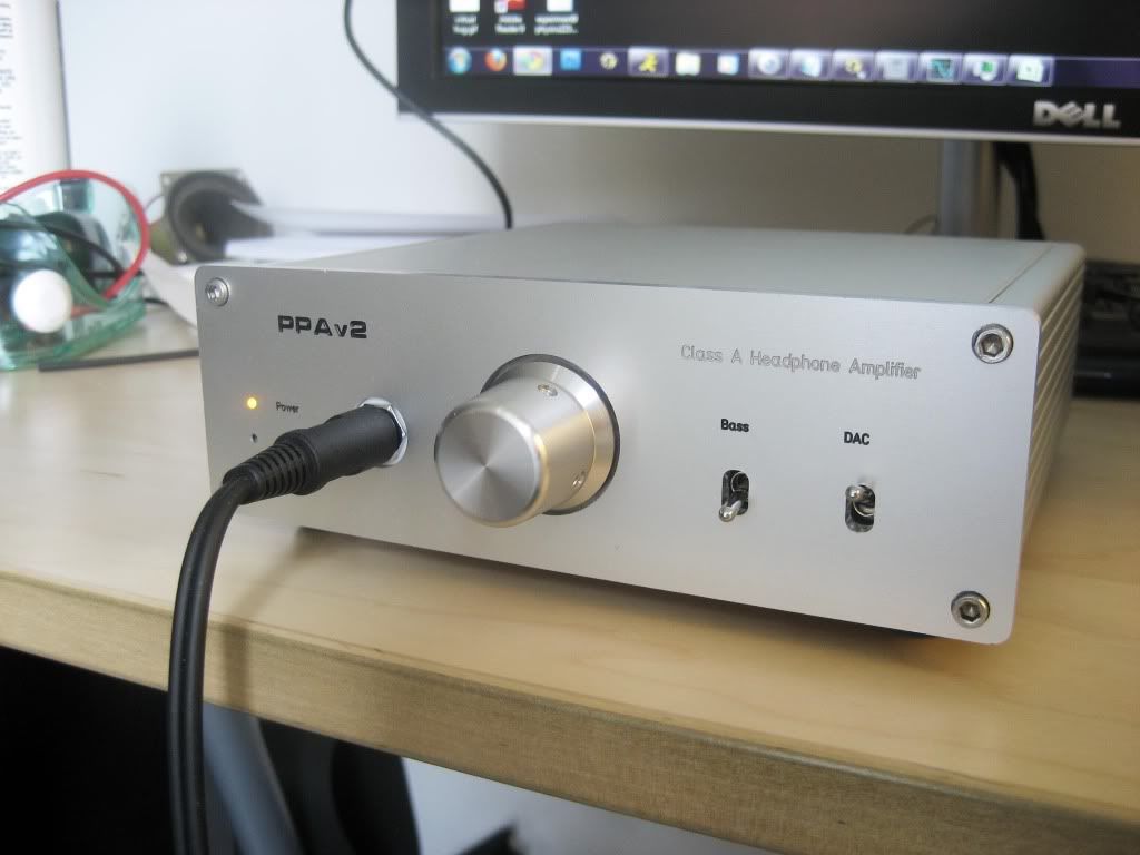
I think PPA v2 is a high end amplifier, it is very transparent, you shouldn't need any better amplifier if you build this.
It should be good for any headphone out there.
 
Apr 29, 2010 at 7:43 PM Post #842 of 1,084
I have a question. I am having a heck of a time obtaining a trim pot so if I'm going with the default parts (including resistors) in my PPA V2, what regular resistors values could I substitute in for the trim pots in R9 and R12? Also, is there a way I could solve for this with a formula, because I'd prefer a bias current of 30-40 mA. Thanks!
 
Apr 29, 2010 at 10:45 PM Post #843 of 1,084
The purpose of R12 is only partly to let you vary the bias current. It's also because there's a second variable in the equation you're looking for, due to the random variation in bipolar transistor hFE.

The best you can do is just try some plausible resistor value, measure the voltage drop across it, calculate current from that, then work out the actual resistor value you want to change it to. I suggest starting with 1K, since that will make the calculations easiest.

As for your difficulty in finding trim pots...I hope you aren't making the mistake of believing you can source all the parts you need without any mail orders. Even people living in Silicon Valley have to mail order parts occasionally.
 
May 3, 2010 at 4:43 AM Post #844 of 1,084
Hey, I forgot to post this last week, but I got my ppav2 working again on the new pcb! I can't thank you enough
bigsmile_face.gif

Only thing left to finish this up is find a missing screw, find a reverse-bipolar LED to mount to the panel, and maybe add a preamp output.

thought I might post some pictures

IMG_1580.jpg

IMG_1587.jpg


Right now, I have a DPDT switch selecting between the y1 dac and whatever's connected to the rca sockets.
Is there some way I can rewire the socket/switch so it can function as a ppa input and y1 output?
I thought about using one throw of the switch and wiring the socket directly the ppa inputs, but that would present two loads in parallel... that would affect the output of the dac, right?.. even if the ppa is turned off.

btw, I also built one of your opamp testers. works fantastically
smily_headphones1.gif


IMG_1593.jpg
 
May 6, 2010 at 6:08 AM Post #845 of 1,084

Quote:
I got my ppav2 working again on the new pcb! I can't thank you enough

 
Yay!
 
Quote:
thought I might post some pictures

 
A truly beautiful build, James!
 
Who made the panel?  It looks like an FPE job, except that the edges aren't shiny.  Has FPE figured out how to do post-machining anodizing since I used them last?  Or, did you send a pre-made anodized plate to them for machining?
 
Quote:
Is there some way I can rewire the socket/switch so it can function as a ppa input and y1 output?

 
I'm not sure what you're asking.  Maybe you should post a quick hand-drawn schematic showing what you'd like.
 
If you're asking whether you can connect one throw of your DPDT to the y1 outputs and the other to a pair of RCAs for direct analog input, yes, that might work.
 
It might be necessary to use a 3PDT instead, so you switch the grounds, too.  This isn't needed if IG in the PPA is tied to the chassis and the y1 is ground-referenced to that, too.  I don't know the y1 design, but digital being what it is, I suspect it needs a different ground.
 
Quote:
I also built one of your opamp testers. works fantastically

 
Yes, for the price, it's good test equipment.  One could conceive of a better tester but that starts getting more costly than the price of a mail order for more op-amps.
 
May 6, 2010 at 10:36 AM Post #846 of 1,084

Quote:
Yay!
A truly beautiful build, James!

Thanks! and it sounds amazing as well 
smile_phones.gif


Quote:
Who made the panel? It looks like an FPE job, except that the edges aren't shiny. Has FPE figured out how to do post-machining anodizing since I used them last? Or, did you send a pre-made anodized plate to them for machining?

It is indeed a FPE panel.  The edges were shiny when I first sanded it down but over time, it somehow developed a slightly matte/anodized appearance.
 
 
Quote:
I'm not sure what you're asking. Maybe you should post a quick hand-drawn schematic showing what you'd like.
If you're asking whether you can connect one throw of your DPDT to the y1 outputs and the other to a pair of RCAs for direct analog input, yes, that might work.
It might be necessary to use a 3PDT instead, so you switch the grounds, too. This isn't needed if IG in the PPA is tied to the chassis and the y1 is ground-referenced to that, too. I don't know the y1 design, but digital being what it is, I suspect it needs a different ground.

That is exactly how it is currently wired up - the ground is tied together and the switch selects between the y1 and RCAs to feed the ppa.  
This is what I had in mind earlier- 
http://img.photobucket.com/albums/v404/reihn/switch.gif
with the switch open, I can take a analog input from the RCA pair.
With the switch closed, I could use the RCA sockets to hook up the output of the y1 dac to a external device or amplifier .. (effectively the same as using a y-splitter cable).  should there be any problems with this wiring?
 
 
Quote:
Yes, for the price, it's good test equipment. One could conceive of a better tester but that starts getting more costly than the price of a mail order for more op-amps.

Definitely.  The opa627's are pretty pricey - $75 for the three.  The opamp tester cost me 44 cents and a few spare parts :)
 
May 6, 2010 at 6:26 PM Post #848 of 1,084
Thanks lil-knight.
The case is a common hammond extruded enclosure
 
Instead of the 160x100mm enclosure that actually fits the pcb itself perfectly, I used the 160x160mm enclosure to allow space for the regulator, dac, and extra panel space.
I printed out the pcb layout before picking out a case and to my surprise, I measured/calculated the potentiometer to sit at the dead-center of this particular case.
(i'm actually now curious if tangent planned for it to work out this way)
 
May 6, 2010 at 7:10 PM Post #849 of 1,084

Quote:
(effectively the same as using a y-splitter cable).  should there be any problems with this wiring?

 
At least two:
 
- The y1 might get annoyed if you flip the switch its direction while there's a source plugged into the RCA inputs.
 
- If you're able to avoid such screwups, it still does bad things because it puts the 50K input impedance of the PPA in parallel with the input section of the other amp, which probably has an input impedance on the same order; the interaction between the two isn't likely to be inconsequential.  At minimum, the volume level of the other "sink" is likely to change as you rotate the PPA's volume knob.
 
You can avoid both problems by adding a second set of RCA jacks, connected to the y1's outputs, keeping the current switch arrangement.  They're thus live only when the switch is in the y1 position.
 
If this doesn't work because the RCAs are floating when the switch is in the other position, you can fix it by putting some high-value resistors to ground from those RCAs' center pins.  1M, say, just to act as weak pull-downs.
 
Quote:
i'm actually now curious if tangent planned for it to work out this way

 
Nope.  That version of the 1455 didn't even exist when we designed PPA v1.  They've added several new sizes since those days.
 
May 17, 2010 at 7:58 AM Post #850 of 1,084
OK everybody, time to make my contribution to this thread.
 
Last Friday, I received the board for the PPA from Tangent, including ALPS pots + TREAD board.
 
This was actually my first serious DIY electronics build ever, and I succeeded! Thanks to everyone contributing knowledge, instructions etc. etc. Special mention for Tangent's excellent webpage with part selection guide, build instructions etc. etc. Actual build time was around 3 hrs. Was succesful on first power up, thanks to excellent step-by-step build guide.
 
The amp is running @ 21.5V, using 3xAD8610. Output buffer bias is set to 20mA, but will up that to 30mA tonight just for the fun of it. Will be adding a battery board somewhere this week (16*AAA), running off 24V from wall wart.
 
Also, I have biased into class A, but I migth have overdone it: from reading this thread, going above 1 V drop across R10 (=1k) really shouldn't be necessary. Thing is: I have trouble hearing any difference; I'll try reducing voltage drop across R10 to close to 0, see if that gives audible change.
 
Question, though: the max voltage drop across R10G I can create using R9 pot is about 1.8. R10L/R10R max out at only 3.3V. Is this difference in adjustability normal/by design?
 
Another question: I have added a fixed bass boost, R7=10k, C7=0.1uF (6dB boost). I can not say that I find the functionality of the bass boost very pronounced. I even wonder if it is working at all, considering I have difficulty telling whether it is on our off. Any pointers for obvious places to look?
 
The build has been very much fun. Somebody I can build a PPA for? :)


May 17, 2010 at 11:27 AM Post #851 of 1,084
Quote:
Special mention for Tangent's excellent webpage with part selection guide, build instructions etc. etc. Actual build time was around 3 hrs. Was succesful on first power up, thanks to excellent step-by-step build guide.

 
Thanks!
 
Quote:
I have trouble hearing any difference; I'll try reducing voltage drop across R10 to close to 0, see if that gives audible change.

 
Consider adding a 3PST switch across R10 instead.  When "on", it switches the resistors into the circuit, enabling the biasing.  When "off", R10 is open, so you get no bias.
 
 
Quote:
the max voltage drop across R10G I can create using R9 pot is about 1.8. R10L/R10R max out at only 3.3V. Is this difference in adjustability normal/by design?

 
Yes.
 
If JFETs weren't so variable in their Idss, we could have done without the R9 trim pot in the PPA.
 
PIMETA v1 dealt with this a different way, by requiring hand-matched JFETs, which in turn meant a fixed bias level.  The PPA scheme is superior, being adjustable, but is more costly both in terms of parts (3x trim pot) and board space.
 
PIMETA v2 deals with this same problem an entirely different way by using a different CCS design which lets all three channels be adjusted from a single pot.  The downside there is that applying that to the PPA would pretty much require moving to a 4-layer design, doubling the board cost.
 
It's all tradeoffs.  There is no single perfect solution.
 
Quote:
I have added a fixed bass boost, R7=10k, C7=0.1uF (6dB boost). I can not say that I find the functionality of the bass boost very pronounced. I even wonder if it is working at all, considering I have difficulty telling whether it is on our off. Any pointers for obvious places to look?

 
That gives only 3-6 dB of boost down in the true bass regions.  To hear the difference, you need headphones with strong bass response -- not "bassy", just not weak -- and music with actual bass.  I don't see any music preferences in your profile, so I don't know which artists or tracks to suggest.
 
May 17, 2010 at 4:56 PM Post #852 of 1,084


Quote:
That gives only 3-6 dB of boost down in the true bass regions.  To hear the difference, you need headphones with strong bass response -- not "bassy", just not weak -- and music with actual bass.  I don't see any music preferences in your profile, so I don't know which artists or tracks to suggest.


I have added my music preferences (mostly Pink Floyd, Radiohead, U2 of mid-90s). I have tried Massive Attack - Mezzanine - Angel. Will the last song do? I *think* I heard a change when turning on the boost. BTW, headphones are Sennheiser HD 555.
 
May 17, 2010 at 6:53 PM Post #853 of 1,084
I don't see the music prefs in your profile, but Pink Floyd gives me all the material I need.  I found three tracks for you to try:
 
  1. San Tropez (studio) from Meddle - nothing jaw-dropping, just a good bass line to work with
  2. Run Like Hell (live) from The Delicate Sound of Thunder, about 1:20 where the drums kick in
  3. The Dogs of War, either live off DST or studio from A Momentary Lapse of Reason - the real cello that starts up after the growling at the beginning is better than the electronic one on the studio cut, but both were noticeably different when toggling the bass boost
 
I used my main PPA with K1000s and a decent outboard DAC for this test, so it's not exactly a fair comparison with your system, but there should be some difference to be had on these tracks.
 
Mind, this feature is only meant to fill in the bottom end on weak bass recordings, not make you believe someone secretly installed a sub under your listening chair.
 
If you added input caps, that counteracts the bass boost feature unless you set the corner frequency very low.  Output caps in your PC's sound card can do the same thing.
 
 
By the way, if you don't have DST, get it.  It's the best live album, ever.  Disclaimer: I hate Radiohead, so let that guide your interpretation of my opinion. :)
 
May 18, 2010 at 2:47 PM Post #854 of 1,084
I did get a copy of DST, but couldn't tell bass were on or off with Run Like Hell. However, I think it is best to wait until I have constructed my DAC board before any further testing. Maybe my setup is a bit too low-end to be judging bass-boost :)
 
I surely will return here in about a month or so.
 
 
Jun 21, 2010 at 4:20 PM Post #855 of 1,084
Hi
 
I was wondering if somebody has tried the Burson Audio Single & Dual Op-amps in their PPA? It would be interesting to hear how they compare to lets say a AD8610, or a OPA627/37. I am planning to build a PPA V2, so it would be nice to know if they will function in the PPA V2 design. I guess they will, but I am just asking so that I don't do something stupid, after all the single op-amp costs 48,50 £, and the dual op-amp costs 78,50 £ at http://www.hificollective.co.uk/components/bursonaudioopamps.html
 
Thanks
vgjako
 

Users who are viewing this thread

Back
Top