PCM2704 USB DAC
Jan 13, 2006 at 2:39 PM Post #16 of 48
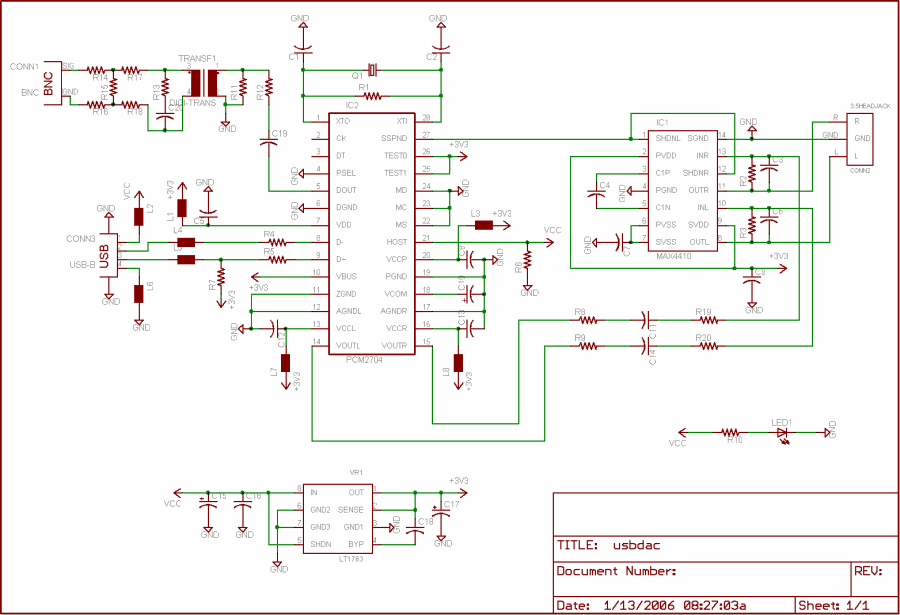
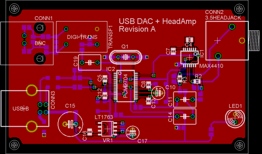
OK, here's (hopefully) my final revision before attempting a proto. I've tried to clean things up more and I also mitered all the corners and made sure the silkscreen is good to go. As always, comments/suggestions appreciated
biggrin.gif


Schematic:
usbdac_sch3.gif


Layout:
usbdac3.gif
 
Jan 13, 2006 at 4:27 PM Post #17 of 48
Your C15 should be going to ground, not in series with the Vcc trace. Won't work as it stands! Inductors on the USB data lines aren't a terribly good idea as they will blunt the pulses, possibly leading to errors. Resistors are sufficient to isolate the PCM. I would recommend not having the Dout trace crossing the crystal trace as well; the crystal trace is the most sensitive on the board
 
Jan 13, 2006 at 5:25 PM Post #18 of 48
Thanks for the reply!

The C15 label actually applies to the large electrolytic cap, not the bottom layer. Sorry for the confusion there...that bottom layer is actually a ferrite. As for the ferrites in the data lines, I guess I could try it with them jumpered and with them in and see what happens for now. Finally, I think you're right about the DOUT line...I never liked crossing the clock signal with that for fear of contamination on either of them. I'll see what I can do to rework that section. Thanks!

EDIT: I found these for possible use on the data lines. Sourcing could be difficult if they don't sell in small quantities (they only sell direct). I also found these which would not only provide me with the 22R resistors, but also with the pullup for D+ and some filtering.
 
Jan 15, 2006 at 5:21 PM Post #19 of 48
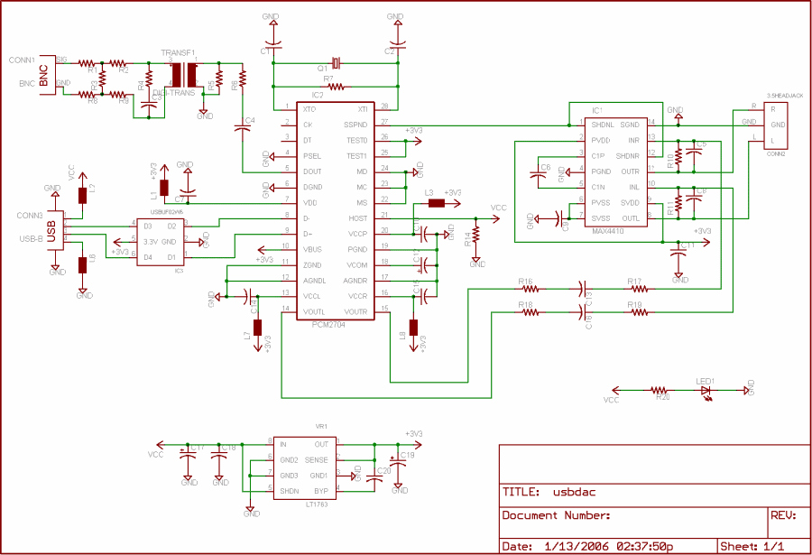
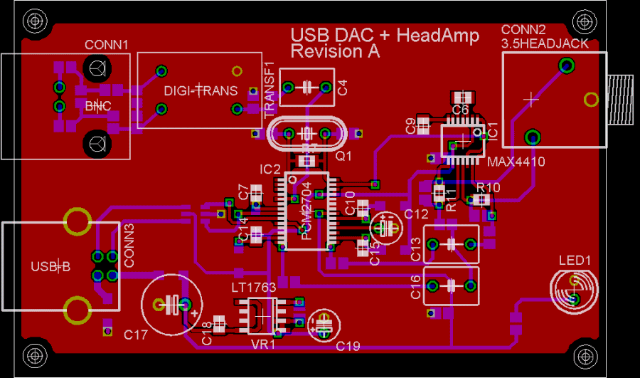
OK...here's the final edit before I submit today for a proto. I added the small USB termination/filter IC that I linked to in my previous post and also tried to improve some of the routing.

Schematic:

usbdac_sch4.gif


Layout:

usbdac4.gif
 
Jan 16, 2006 at 12:34 AM Post #20 of 48
There is plenty of room to have the digital output go up the left hand side of the chip, then put the resistor across the crystal there on the bottom layer and move the crystal in as close as you can
 
Jan 16, 2006 at 6:18 PM Post #22 of 48
Ahh...both good ideas. I put in the order for the proto before implementing either of them, but I will most likely make the changes for a future version.

Oh and DaKi][er...thanks for that link (not sure when/where it was posted) for BatchPCB. It is hands down the best place for this type of thing
smily_headphones1.gif
 
Jan 19, 2006 at 3:19 PM Post #23 of 48
Just a quick update/FYI for anyone interested...

I contacted TI tech support concerning the output impedance of the DOUT pin on the PCM2704 and also asked about the PCM290* as well. Here's what they had to say...

Quote:

We do not have maximum value for this spec, but the estimated maximum values are +/-30% of 50ohms. This is the case for the PCM27* and PCM29*.


Doesn't narrow it down too much, but it's better than nothing I suppose...
 
Feb 1, 2006 at 11:02 PM Post #27 of 48
Got the board today along with the MAX4410's I ordered from Maxim. I'll try and get some shots posted later tonight. Hopefully, the rest of the parts will be here tomorrow and I can get it built by the weekend. Woohoo
smily_headphones1.gif
 
Feb 2, 2006 at 5:13 AM Post #28 of 48
Quote:

Originally Posted by ble0t
Ahh...both good ideas. I put in the order for the proto before implementing either of them, but I will most likely make the changes for a future version.

Oh and DaKi][er...thanks for that link (not sure when/where it was posted) for BatchPCB. It is hands down the best place for this type of thing
smily_headphones1.gif


batchpcb is very very slow - often taking more than a month. 4pcb.com does much better boards of pretty much any size in a week for $33 if you're a student. (and they actually know what customer service is too)

Anyways - one thing that bothers me about your design: where are the thermals? I expect you'll have some trouble soldering some of those parts that are connected to the groundplane - it'll just act like one big heatsink.
 
Feb 2, 2006 at 1:48 PM Post #30 of 48
nleahcim: I ordered from BatchPCB on Jan 15th and got my board yesterday. Two weeks for double sided soldermask and silkscreen isn't bad turn around if you ask me
smily_headphones1.gif


As for the thermals, I didn't have any issue soldering on Alf's board and I wouldn't expect much here. It's a question of 'local' heat, and the groundplane isn't thick enough and/or big enough to dissapate enough heat to prevent soldering.

chaostic: No, they never asked me anything like that. When I submitted my request, they asked me (in a web form) for my name, address, etc.

Lastly, here are links to some scans of my board if anyone is interested...I hope to get some soldering done tonight
biggrin.gif


Top
Bottom
 

Users who are viewing this thread

Back
Top