PCM2702 USB DAC Revision B
Jun 23, 2006 at 3:02 PM Post #616 of 670
Quote:

Originally Posted by threepointone
icon10.gif


so do i go for the one with the lowest ppm rating or most zeroes, or what?


A quick google turned up this:

http://www.sparkfun.com/cgi-bin/phpb...4eaa9aafb2b300

The lowest ppm = the highest accuracy.

Please someone confirm
smily_headphones1.gif


Rob.
 
Jun 25, 2006 at 8:38 PM Post #618 of 670
Some pictures...

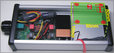
1. It started with an idea:
Pimeta-USBDAC-1.png


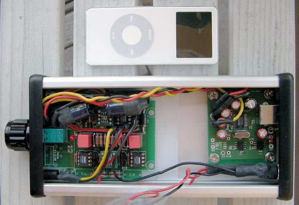
2. And it turned out to work well!
600smile.gif

Alien_Pimeta007_bewerkt.jpg

Not exactly portable compared to the iPod, but it is transportable with a laptop.
When placed upside down tangents crossfeed (with orange drops) can be installed, though Foobar2k can do similar things with plugins. I prefer having a 9V battery for the AMP (7-8 AAA batteries will also fit) for portable
icon10.gif
use.

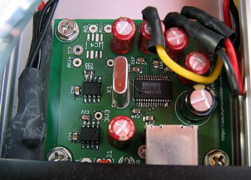
3. I used some carafines that I happen to have. The SMD soldering was a first time try.
Alien_Pimeta006_bewerkt.jpg
 
Jun 26, 2006 at 6:07 PM Post #619 of 670
i couldn't resist and ask ti technical staff about the vcom pin, i received the following answer:
---------------------------------------------- 8< ----------------------------------------------
Vcom-pin is prepared for just noise de-coupling function of internal 0.5Vcc DC bias
which is generated by simply resistor network as shown in below.

Vcc---
|
R= 40K
|-------- Vcom-pin
R= 40K
|
GND

Therefore, if connected low impedance DC load, 0.5Vcc bias would be shifted.
It accepts connection high impedance DC load such as non-inverting(+) input
of OmAmp.
---------------------------------------------- 8< ----------------------------------------------
 
Jun 27, 2006 at 3:25 AM Post #620 of 670
Quote:

Originally Posted by t52
i couldn't resist and ask ti technical staff about the vcom pin, i received the following answer:
---------------------------------------------- 8< ----------------------------------------------
Vcom-pin is prepared for just noise de-coupling function of internal 0.5Vcc DC bias
which is generated by simply resistor network as shown in below.

Vcc---
|
R= 40K
|-------- Vcom-pin
R= 40K
|
GND

Therefore, if connected low impedance DC load, 0.5Vcc bias would be shifted.
It accepts connection high impedance DC load such as non-inverting(+) input
of OmAmp.
---------------------------------------------- 8< ----------------------------------------------


so would that mean that it should be fine to use the Vcom pin as ground when connecting with an amp w/o any decoupling caps?

or better yet, couldn't we just make a virtual ground with the standard tle2426 circuit and avoid the decoupling caps even without an amp?
 
Jun 27, 2006 at 3:33 AM Post #621 of 670
Quote:

Originally Posted by threepointone
or better yet, couldn't we just make a virtual ground with the standard tle2426 circuit and avoid the decoupling caps even without an amp?


I was just about to ask that....

Would make life much easier.

Rob.
 
Jun 27, 2006 at 1:18 PM Post #622 of 670
You could, but doing so would defeat the purpose of this design, ie, simple and portable. Putting in a railsplitter would require you to buffer it to drive the full current requirement of the PCM2702 and headphones, and you'd waste half the supply on just opamps.

The Vcom pin, being simply generated by a resistor divider is not stable, and as Alf's measurements have shown, not necessarily balanced on both sides. I don't understand the objection to having to install capacitors in this design
 
Jun 27, 2006 at 3:03 PM Post #623 of 670
Quote:

Originally Posted by guzzler
The Vcom pin, being simply generated by a resistor divider is not stable, and as Alf's measurements have shown, not necessarily balanced on both sides. I don't understand the objection to having to install capacitors in this design


You make a good point. This is just a simple plug-and-play diy DAC (not that its a bad one mind you!). However if there is a simple tweak one could do to improve "performance" then why not?

A TLE requiring buffers and opamps and all that jazz is, i agree, overboard for what this DAC really is. Can i just throw this suggestion into the air though? What if one used a TLE to create a reference for output ground only? Keep the PCM operating off the same voltages, but reference its Vout to 2.5volts as created by a TLE?

(Of course, this does draw into question just how well the PCM "centers" its output)

Rob.
 
Jul 1, 2006 at 2:44 AM Post #624 of 670
A quick question -

For C1, the range of values are 1uF to 22uF. Is there an "optimal" value? What kind of a difference can I expect with differing filter cap values?

Thanks in advance!
 
Jul 1, 2006 at 4:03 AM Post #626 of 670
Quote:

Originally Posted by robzy
I found 0805 ceramic capacitors to be quite expensive in that range, so i just went for the cheapest.

(I'm not really answering your question though)

Rob.


Actually... the Kemet Hi-cap range of ceramics are not that bad.

22uF 6.3VDC X7R 20% (Mouser: 80-C0805C226M9P) $1.40
10uF 10VDC X5R 10% (Mouser: 80-C0805C106K8P) $0.50

Given that you only need two... $1.4 isn't too bad, I thought. 10uF caps are a dollar for two so that's even more reasonable.
 
Jul 1, 2006 at 4:40 AM Post #627 of 670
Also, another quick question about C13...

Can I use a 330uF Panasonic FM part here? The suggested values are 10~47uF, is it necessary to stay within these bounds?

I'm a bit more "sure" about using the 330uF part for C23 although the suggested values are up to 100uF... but I'm not too sure about C13.

Again, thanks in advance!
 
Jul 1, 2006 at 5:04 PM Post #628 of 670
C1 doesn't really have an optimum value unless you calculate all the parameters for the filters and coupling to USB line, 1uF will do fine.

C13 just couples the internal "ground" to the real ground, no point in going larger than recommended here.
 
Jul 1, 2006 at 6:01 PM Post #629 of 670
Quote:

Originally Posted by guzzler
C1 doesn't really have an optimum value unless you calculate all the parameters for the filters and coupling to USB line, 1uF will do fine.

C13 just couples the internal "ground" to the real ground, no point in going larger than recommended here.


Thanks for the reply!

Regarding C13... 330uF is the ONLY value available for 6.3V and 6.3mm diameter for the Panasonic FM line which I would like to use... I thought that if there is no point (i.e. no harm done) in using the larger value that I just would use it... better than trying to get a lower value by going up the voltage rating.
 

Users who are viewing this thread

Back
Top