I never understood either why many dislike the electrolytics in that role. Electrolytics are at the output of the Woo OTLs....and they sound just fine. At 470uf, the bass response is subsonic.
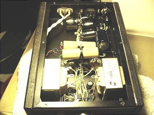
I ended up with a pair of those Hammonds after reading your thread....I still need to get them in a classy enclosure.
They make compact low-ESR electrolytic caps, but I am not sure why these are generally unaccepted for this application.
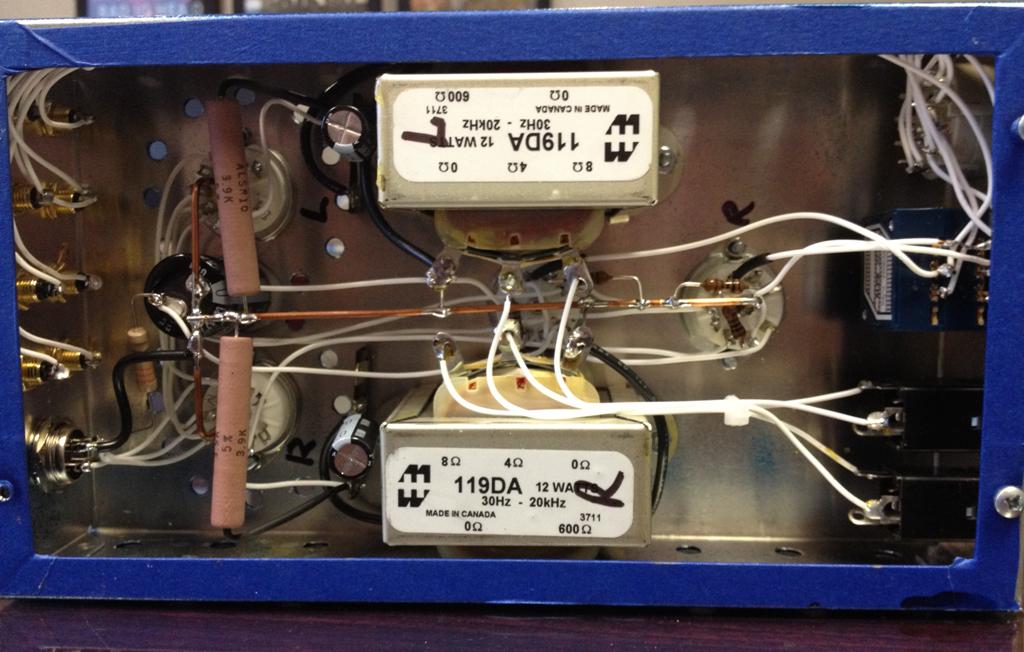
.......Hammond 119DA 12W speaker transformers, with the 4 and 8 ohm secondary coils powering the HI/LO-Z headphone jacks
Kramer speaks truth. OTL amps are at a disadvantage when it comes to low-impedance phones and the reason is not roiled up into impedance mis-matches. Bass cutoff is a reality and depends on how big a capacitor you can hang off the output. Electrolytics in high-value uf's are generally more economical (film caps aren't even possible in some ratings - like the beer can analogy he used). In an ideal situation, the reason electrolytics are not favored however, is that compared to output transformers or film capacitors, they put a
fog over the music, literally. They are simply magnitudes less transparent and inherently higher in distortion.
Dsavitsk favors parafeed output-transformer amps and full-disclosure: I sell one of his designs: the Torpedo. He sold a parafeed, too - under ECP Audio: the L-2 (see the Summit-Fi forum section). Tyll mentioned it in his Abyss headphone review as an ideal pairing with the HD800 (he setup a shootout scenario). A parafeed output-transformer design still uses interstage coupling capacitors, but because of the connecting impedances (output transformers) the requirement for uf's is very low. The Torpedo uses 4.7uf coupling caps, for instance, which are well within range of film capacitors - maybe half the size of a roll of lifesavers, for instance. The transparency with film capacitors is monumentally superior to an electrolytic. Just for a magnitude comparison, note that
four hundred seventy uf's are quoted up there, compared to a
four-point-seven uf film capacitor in a parafeed, output-transformer design.
With OTL amps, the connected load impedance (headphones) makes all the difference. That's not because of the impedance interaction - it's because the headphone impedance combined with the output coupling capacitors forms
a textbook-classic RC circuit. Such a circuit is frequency-dependent for current flow. IOW, frequencies too low will not pass (high-pass filter). In the case of typical headphone impedances, even 470uf means bass cutoff is beginning at about 110Hz. At 20Hz, it's down by more than 1dB. That doesn't sound like a lot, but remember that we're used to ruler-flat responses in amplifiers from subsonic to almost 40-50KHz, or more. There are phase distortions that occur well above that 110Hz, meaning the bass is affected well into the range where 32 ohm headphones would be affected
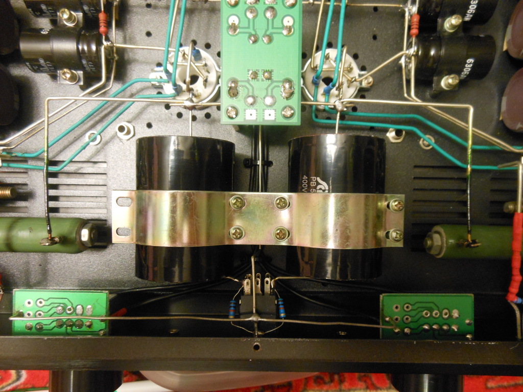
Here's a shot that can illuminate the issue. Remember what Kramer said - even 470uf electrolytics are huge at 200-300V, and there are none that are considered "audio-quality" (Black Gates, Nichicon Muse, Elna Silmic's, Cerafines, etc.):

For comparison's sake, many OTL amps use only 220uf electrolytic output capacitors. They get away with this because they
expect people to use high-impedance headphones with it:

As you can see, even not counting for any phase distortions, bass is severely affected at almost every impedance except for 300 ohm.


")

