[ortho transplant] "Orthosex": SFI into AKG K240 Sextett LP (in progress)
Aug 30, 2011 at 10:26 PM Thread Starter Post #1 of 51

Armaegis

Modern Modder Man of Manitoba
HTML... uphill, both ways!
Joined
Oct 18, 2009
Posts
12,546
Likes
1,402
 
the drivers: ortho SFI 120 ohm 
the foster home: AKG K240 Sextett LP
 
Let's start with the disassembly...
 
 
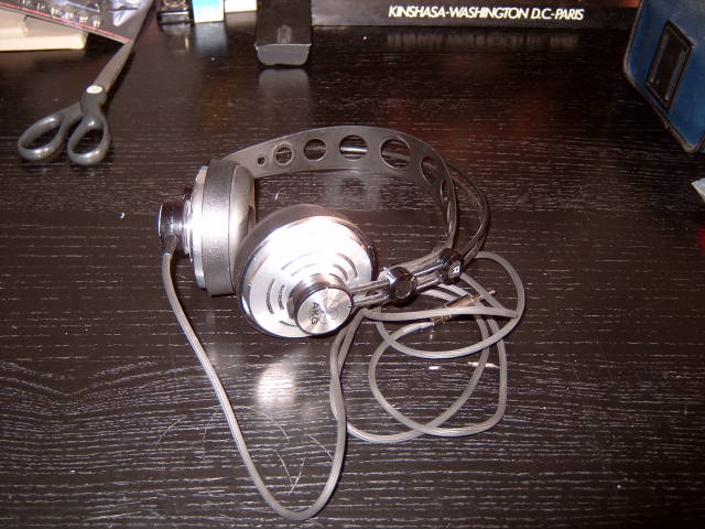
1. Here's the shiny not-so-new Sextett that I purchased without drivers

 
2. Use a thin hobby knife to peel off the badge. The badge is a thin metal piece, so be careful not to bend it. There may be some glue residue beneath which obscures the screw. That's ok, just use your knife or a screwdriver and gently scrape away until you can see the screw. Actually, don't even remove it all; just take out enough that you can reach the screw and turn it, the remaining residue will hold the screw partially in place so you won't lose it. You know what they say about little screws...


3. Lift out the cap and screw to reveal... another screw! I think there's a joke here about a screw that screws into another screw in the Sextett, but let's be adult about this. Take this one out too and the cup will come loose. The headband elastics also attach at this point; note the slight ridge on the headband end. When you reattach the headband, make sure the elastics are resting on the ridge and not the screw. Nothing worse than having something snapping your ridge. 

 
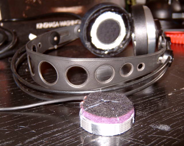
4. Disassembled picture; if you look closely you can see that those are not original elastics. They are hair ties that were overachievers, so they were cut short and knotted to put them in their place. You can hide the knot inside the cap during reassembly to hide your dirty dirty deed. 

 
5. Lift out the rear cup and you'll see the mounting bracket (the thing with four holes), which is attached to a ring gimbal, which is attached to the front baffle. This neat assembly is what gives the cups their seemingly circular range of motion. The two side holes fit into the mounting tabs on the rear cup for stability, the bottom hole is where the wires go through. The centre hole is from the screw, where the screwing happens obviously

 
6. Using a knife or fingernail, pry off the outer ring. I found that there was a small notch on one side which made it easier to get my finger in. Wiggle gently. 

 
7. Gently pop off the bracket. It will be easier to bend the ring gimbal than the bracket as the gimbal is softer. Be careful not to squeeze too hard though; this is a delicate thing after all. There's a lot of deteriorated crud inside. This is what happens when you don't clean your sextett regularly

 
8. You can also pull off the front grill. Either pry up the edges from the front, or gently push down the middle from the back. I said gently! If things bend rather than push through, you may need to rethink your exit strategy.

 
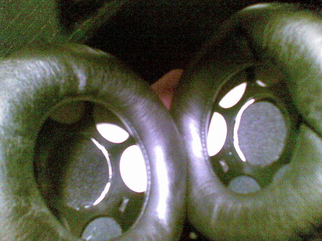
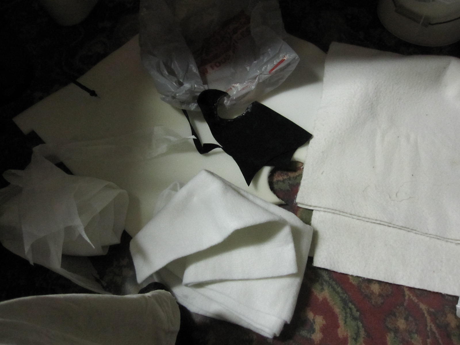
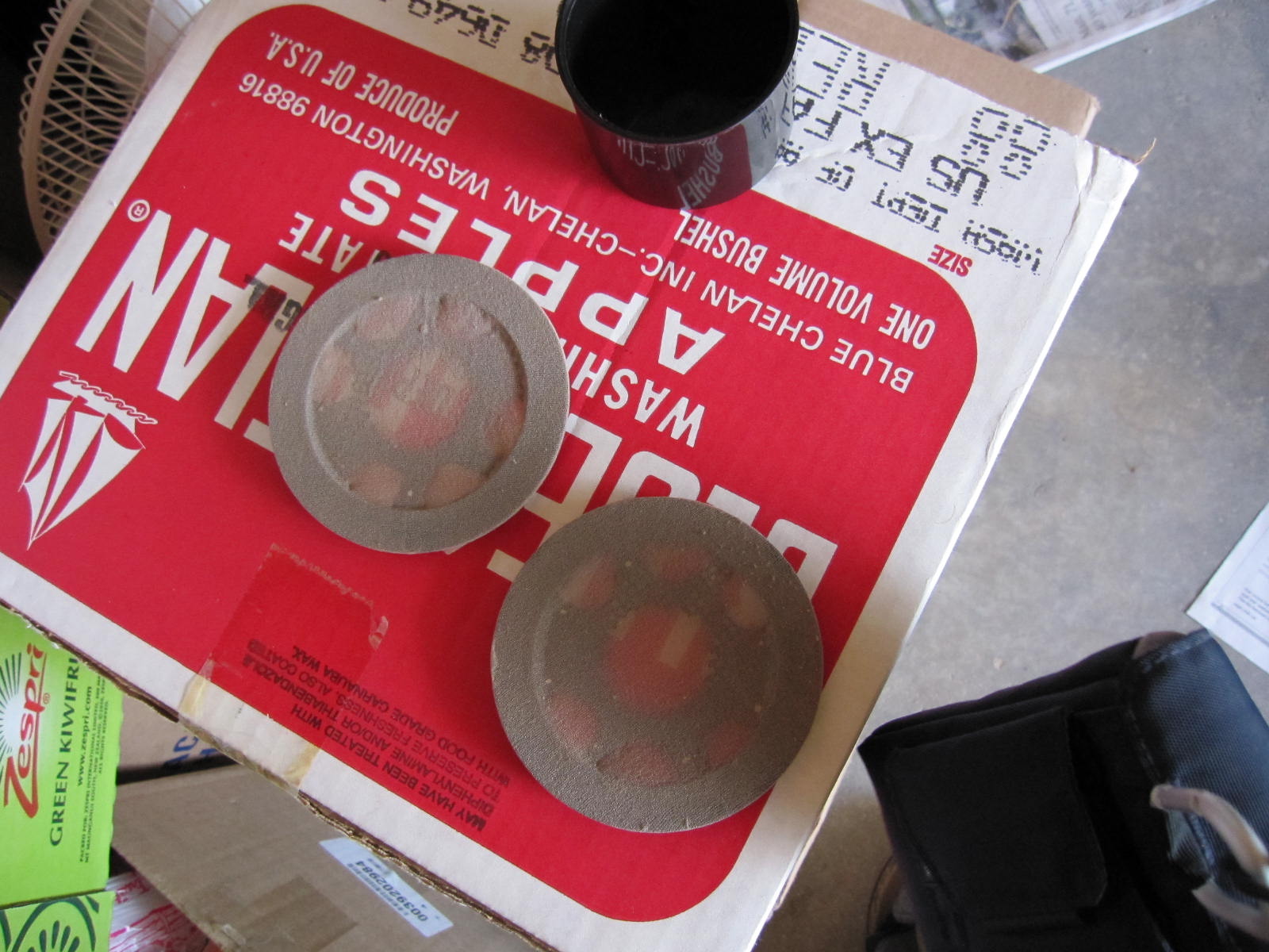
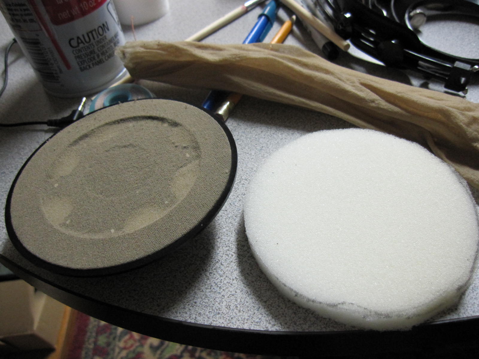
9. Here are the naked diffusers that give the Sextett its name. Sometimes they come in different colours. Please resist the urge to poke them. I know it's exciting when there are three pairs in front of you, but do control yourself. You'll get a chance to open things up for them later.

 
10&11. More shots of the crud. You really should remove this as it's just going to disintigrate


12. Here's the gimbal assembly with all the crud removed. Note the inner 35mm diameter wall, this is where the driver normally goes. Since the driver I want to use is 40mm, it cannot be mounted here. I decided here to mill out the 35mm wall, then opted to mount the driver into the ring gimbal which I figured would be easier than trying to glue it down to the baffle. 

 
13. A bit later with a dremel and voila, all reamed out and noticeably wider and a little rough around the edges

 
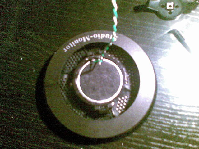
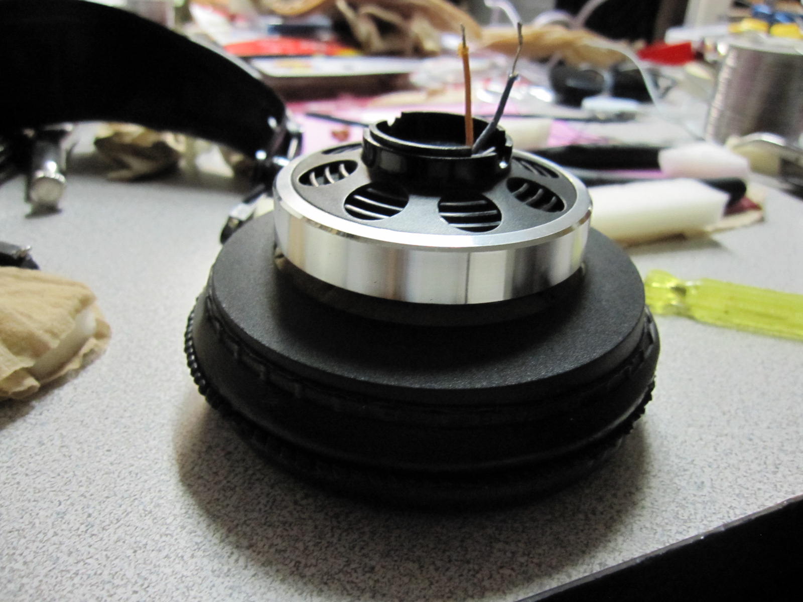
14. Here's the SFI driver sitting on top of the gimbal. There is maybe 1mm is clearance here. I considered cutting out small slots in the ring gimbal so the leads could settle deeper and let the driver sit deeper in the ring, but I was not comfortable weakening the ring.

 
15. Here's the front baffle all by its lonesome because that hussy gimbal ran off and filled its hole with a big SFI. 

 
16. But it turns out that the gimbal is a little too loose of a fit for the SFI, so a thin layer of hot glue is applied. Drop down a very small bead then use the hot nozzle to wipe a thin flat layer around the inner edge


17. But make sure to rough up that inner surface with some sandpaper or a dremel first, otherwise the glue layer slips right out. Oops. We wouldn't want any accidents now.

 
18&19. Then slide that baby in. You might have to push a little harder since the fit is much tighter now. As always, be gentle. If you break it, you don't get a second chance.


20. Depending how comfortable you are with bending the gimbal mount tabs on the front baffle, it may be easier to mount the gimbal first, then the driver later. If the driver is mounted first, the gimbal becomes inflexible and is very difficult to snap into the front baffle. After that, reattach the bracket. This is also going to be an extremely tight fit, and I had to dremel the mounting pegs a little shorter and also use a pair of pliers to squeeze everything down so I could reattach it. You will lose the one axis of freedom here because the driver presses up against the bracket so it cannot rotate freely. If one were to mount the driver deeper in the gimbal, I'm sure we could regain that freedom, but as I mentioned before this will require some very careful drilling of the gimbal. If I were to attempt this project a second time I would probably do so, but right now it's all attached and I would really rather not attempt to disassemble it at this point. 

 
21. There is a tiny bit of clearance between the bracket and rear of the driver. This isn't ideal, but at least there's some breathing room. I plan on putting some micropore tape or perhaps sticker felt on the underside of the bracket just to absorb some of the rear projection from the driver.


[more to come]
 
Aug 30, 2011 at 10:26 PM Post #2 of 51
22. Next up, chopping out some of that front grill. I figured hard plastic doesn't do any favours for the sound passing through, so after some rather energetic work with a dremel, we're left with this. I could have chopped out a bit more, but man controlling a dremel is hard when you're going through irregular material by hand. I was also erring on the side of caution, as the plastic was starting to feel a little weak after putting all those big holes in it.

 
23. Here's how it looks. I could have chopped out a bit more, but man controlling a dremel is hard when you're going through irregular material by hand. I was also erring on the side of caution, as the plastic was starting to feel a little weak after putting all those big holes in it.

 
24. With the grill cut up though, there isn't much protection left for the driver. Figured I'd glue some nylon pantyhose over them which I'm told are acoustically transparent. I picked up some spray glue from an office supply shop, and an old set of nylons from mom (seriously, she gave me an entire bag; I think I have enough to fill a subwoofer).

 
25. Out to the garage I went with some newspaper. I sprayed the entire front and the backside rim (just used a small cut out paper circle to block the grill backside when I sprayed). One quick pass with the spray is all you need, and the glue dries fairly quickly so you have to act fast. 

 
26. Gently stretch out the nylons over top and wrap and smooth them out, then wrap them over the edge and trim off the excess. Be careful not to overstretch the nylons in your excitement. You don't want to be the guy who stretches too hard and rips it do you? And then you'll be left with a sticky mess on your hands. Also, transfer the grills to a clean and glue-free surface before attaching the nylons, otherwise you'll wind up glueing the stockings down to the table/newspaper/etc. Ask me how I know. Alternatively, stretch out the nylon on a makeshift frame beforehand, then quickly plop the gluey grills face down on them and work from there.


28. Mount them like you mean it. 

 
29. So far this has used up about one "foot" of pantyhose. I took the remainder of the leg and cut it in half, then used that as filler. No idea if this works well or not...

 
30. And I added a piece of micropore tape behind each driver. In retrospect, this would have been way easier to do before attaching the brackets.


31. You know what? that nylon filler really doesn't do anything. So I scrapped up some foam and cut it into a strips and circles. The strip will go into the ring, and the circle into the rear cup.

 
32. I decided to wrap the foam strip in the pantyhose. This was surprisingly difficult to do. It's so much easier taking those things off. Note also in this pic the two thin strips of suede (leftover from when I sueded my own dance shoes). More on this in pic 34.

 
33. Bend it, stuff it, squeeze it in, careful not to let any bits stick out. There is no safeword here, so suck it up and go. 

 
34. I decided to use the suede strip to line the edge of the rear cup. No real reason other than it made me feel fancy.

 
35. I was thinking of glueing it in using some of that spray glue I have, but figured the foam would do enough to hold it in place. I basically just tore out the hole with my fingers; the scissors are useless for small cuts in there. 

 
36. Even with all that foam surrounding and behind the driver, I was still getting really strong treble. Maybe another big piece in front will work?

 
37. Oooff, that's a lot of foam. Something thinner and denser might be better, but I'm workin' with what I've got here.

 
38. This baby is filled to the brim!

 
[more to come]


Aug 30, 2011 at 10:26 PM Post #3 of 51
39. So today I visited my parents and raided mom's sewing cabinet. I managed to find a couple felts (thin and medium thickness). I also found some scraps of foam packing wrap. This stuff is non-breathable, so I figure I can use that to line the walls to make a less reflective surface. The dark patch in the picture is the scraps of suede I mentioned earlier.

 
40. My mission now is to cover up as much of the hard reflective surfaces that I can find. First up is some micropore tape all over the baffle. I was considering taping up the vent areas as well, but for now decided to leave it open.

 
41. Here's a ring of packing wrap along the back of the ring. My reasoning here is that sound will go through felts and foams and still reflect off the hard plastic. Since the packing wrap is non-breathable, it presents a softer surface to reflect sound.

 
42. I used the ring and cup as a stencil to cut out some felt rings, then trimmed a little off afterwards with scissors to make it all fit. 


43. Then just eyeballed the next cut to make the smaller ring. If it's too big, just cut a small wedge out of the ring and close it up. Here you can see both felt rings placed into the plastic ring and rear cup respectively. Assemble with the foams from #31 and #35

 
44. That leftover circle of felt goes on the front over the driver opening. Then next I cut out yet another full sized felt circle and placed that on top, then the foam disk, and squished it all down under the pad so it looks pretty much like it did at #37 but with more stuff underneath.


****************************
 
notes on sound:
 
1) no damping other than the tape on the back and the nylons in the ring, rear cup not mounted
- wobbly all through the midrange and treble
- bass weak
 
2) nylons in ring, tape on rear of driver, rear cup mounted
- bass slightly better, still lean
 
- midrange relatively flat
- starts climbing slowly at 1kHz, rapidly at 2kHz
- very directional tweeter
- slight dip around 400-500Hz (might be reverb dead zone)
 
3) foam+nylons in ring, suede edge along rear cup, foam in rear cup
- bass acceptable
- climbs at 2kHz, but not as hard as before
- didn't notice that dip at the 500Hz anymore
- there's a very small dip somewhere just under 1kHz (maybe it moved? or I created a new one)

 
4) as #3, with foam layer beneath pad
- flatter yet, starts peaking around 4kHz
- overall attenuation from midrange up
- which makes the bass feel stronger relatively
- seriously inefficient now; I've got my receiver maxed
 
5) as #4, plus micropore on hard baffle surfaces, felt and wrapper rings added to outer ring, felt ring added to rear cup, felt disks added to front of baffle
- sounds like #4 but more attenuation and brings the bass up noticeably
- a couple small dips along the midrange; will have to try and localize those later


Aug 31, 2011 at 6:53 AM Post #6 of 51
Great to see them used in an interesting project too--good luck!
 
Aug 31, 2011 at 3:53 PM Post #7 of 51
Hey Nathan, maybe if you remove the front plastic grid in the baffle you will be able to push the driver further and get more clearance for the mounting bracket.
 
Aug 31, 2011 at 4:36 PM Post #8 of 51
Well right now the driver is sitting in the back half of the ring gimbal. It doesn't sit all the way in because the leads stick out and I would have to mill out part of the gimbal to set them further. I considered mounting the driver on the baffle itself, but I couldn't see enough clearance against the gimbal. Bah, it's kind of hard to explain.
 
Aug 31, 2011 at 7:48 PM Post #10 of 51
Hmm, I'll take a closer look. One of the leads on one was already broken; not sure I want to risk losing any more. I'll have to solder a wire uncomfortably close to the diaphragm. Come to think of it, I don't think I'll be able to fit two wires down the edge of the gimbal. 
 
If I were starting over, drilling two holes into the gimbal for the leads and sliding it in that way would have been better, though with the tight clearance I'm not sure if it would have been possible to fit them in that way. Going the slightly destructive route, it would be better to slice the gimbal open, insert the driver, then epoxy it shut. 
 
Sep 2, 2011 at 7:49 PM Post #11 of 51
I bet damping this baby will be loads of fun, IMO the original Sextett had some reverberation problems that was probably multiplied by the radiators. Hopefully it sounds good!
 
Sep 2, 2011 at 8:19 PM Post #12 of 51
I haven't wired it up yet, but initial listening tests with some clip leads (which means I didn't have the back cover on) have some pretty strong peaks in the treble. It reminded me of the Grado peaks actually. Mids felt a little bumpy; reminded me of an Ultrasone 
rolleyes.gif

 
I've got some more pics which I'm going to upload and post in the next hour. 
 
Sep 2, 2011 at 9:12 PM Post #14 of 51
More!!!
 
really looking forward for sound impressions.
 
JoelPearce, are those the one you once told me to buy on ebay? I have 2 pairs around somewhere (failed experiments) I could never get bass out of them, not even a bit. "SFI Tweeter"
 
 
f6c8ac1a_IMG_0395.JPG
 
 
another search only gave me this


Sep 2, 2011 at 9:55 PM Post #15 of 51
 
^ I wish mine were that clean. The set I got from Joel had clearly been through a few experiments already. 
 
Sigh, so once again I think I have some dirt in the drivers. It's only apparent when pushing loud with low end sine waves, but still... 
mad.gif


Users who are viewing this thread

Back
Top