


L_u_k_a_s
New Head-Fier
- Joined
- Feb 25, 2009
- Posts
- 5
- Likes
- 0
Quote:
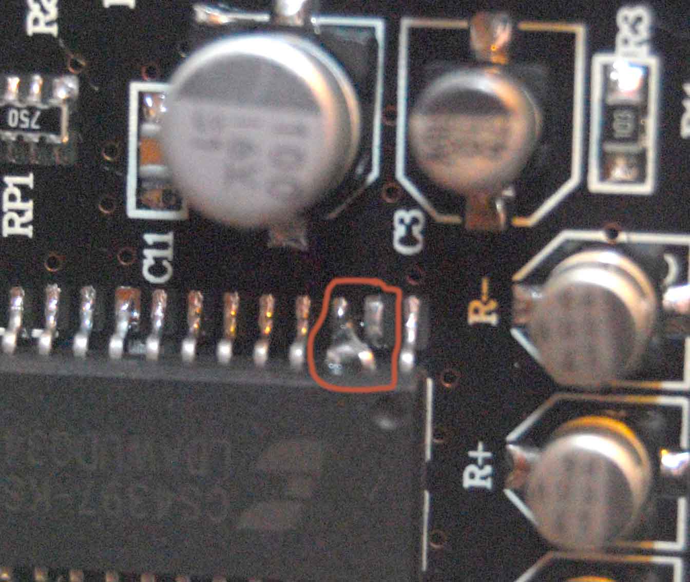
Actually, it is designer's intention. See this reply from seller to my questions about pins 2 & 3 and images attached.
Reply from seller:
hello, i have saw all my dac boards.all the boards are the same .
and i asked the technican .
they tell me that it isn't bad.
it is designed like that.
it is better .
if you don't like that , you can change it by yourself.

| Originally Posted by ericj /img/forum/go_quote.gif Just got one of these, and i have to say, boy, the quality. Where is it?! Pin 2 is lifted and bent over to pin 3 on the dac. Easy to fix, but, gives one the impression that these weren't inspected at all. |
Actually, it is designer's intention. See this reply from seller to my questions about pins 2 & 3 and images attached.
Reply from seller:
hello, i have saw all my dac boards.all the boards are the same .
and i asked the technican .
they tell me that it isn't bad.
it is designed like that.
it is better .
if you don't like that , you can change it by yourself.


