As Tom suggests, you probably don't need to remove those heat-sinks.
There shouldn't be too much problem getting the screws open. May be a little tricky depending on how you installed them, but I'm pretty sure you'll be able to get at it.
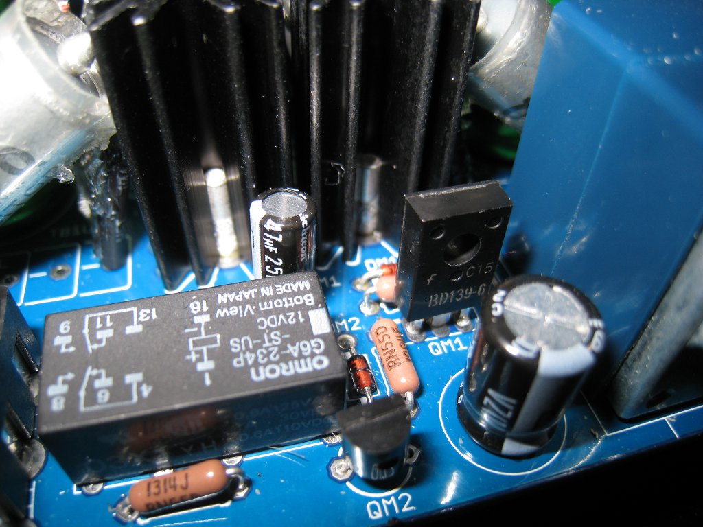
Once you've got those screws out, though, I suggest looping something through the transistors hole, like some wire, or string. Put a *little slack on it while you melt a large blob of solder on the solder points, and get your iron at a good angle to get contact with all 3 pads at the same time. The transistor should elegantly slide out if done right. Don't pull too tight, or you may mess up some pads.
Getting them back in is a little trickier. If you have some solder wick, or a pump, and manage to clean up the holes nicely, it'll be a breeze. Just get the transistor in the right way, screw it in nice and tight, then solder... if you cant clean the holes too well, you'll be doing a somewhat reverse process of getting them out, which.. isn't as sympathetic.