New Millett Hybrid MiniMAX (what happened to this thread?)
May 7, 2009 at 11:31 AM Post #1,171 of 1,948
Quote:

Originally Posted by kugino /img/forum/go_quote.gif
i need some help with DB biasing...

i just finished building the mini max...didn't get any readings while trying to bias the tubes, then realized i had forgotten to jumper RB8/RB9. jumpered them and got a reading for the tubes, biased them to 13.5 (still fluctuating). voltage is steady at 27V.

then, went to the DB biasing...and i get ZERO readout on the MM. a quick power on/power off has a residual of a few mV, but nothing large. i turned the trimmers 15 turns but no increase, so i turned them back down. i checked the power transistors to make sure i had the right ones in the right sockets, and they check alright. i have 2SC3422 in QB8L/R and 2SA1359 in QB9L/R.

any thoughts? right now i have a pair of 12FK6 tubes in there...i thought this might be a trouble-free build, but i guess not. any help would be much appreciated.

update: okay, after poking around this thread, methinks the power transistors are in the wrong direction. if you have the front of the board facing you, the pins are currently in the left-hand slots. i believe for the 2SC3422/2SA1359 pair, the pins have to be in the right-hand slots. correct?


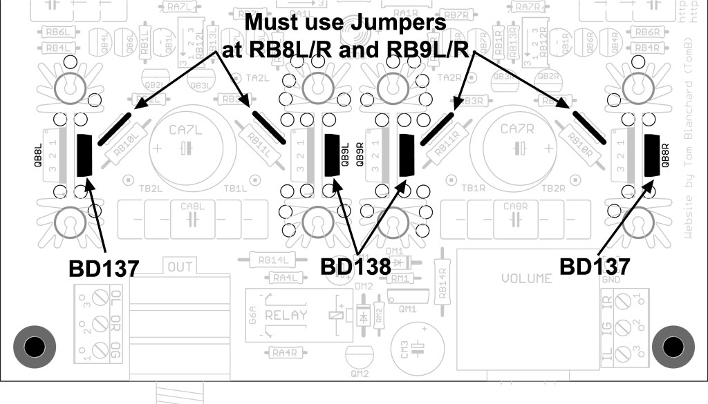
Yes. See pic below from the Output Stage -> BJT Diamond Buffer page of the MiniMAX website:
MiniMAXbjt-positions-sm.jpg


Not to worry - there hasn't been an instance yet where the output transistors have not survived a backwards mounting.
wink.gif
Melt a solder blob on the backside of the board for each transistor - large enough to cover all three pins. If they don't drop right out when the blob is melted, then tie a string through the mounting hole and pull with one hand while you're melting the solder with the other.

Don't worry about replacing the Bergquist pads right now. The 2SC3422/2SA1359 are inherently insulated because they're plastic bodied. The heat transfer efficiency loss won't be bad enough in the short term. When you get more pads, you can remove the mounting hardware again, bend the transistors back slightly, and slip a pad in place. Or, just use some grease.
wink.gif
It think they'll be fine for the short term, though.

Let us know how you fare.
smily_headphones1.gif
 
May 7, 2009 at 8:26 PM Post #1,172 of 1,948
tom, thanks for the info. i finally got all the transistors removed and replaced (pain in the arse!) and was able to get most of the hardware back on. i've biased the tubes (13.5V) and the DB bias on both sides now stands at about 100mV.

however, i cannot get any sound out of the headphone jack. i've tried to make sure the source, rca cables, and headphones are okay, and they're fine. any ideas about what could be the problem? i removed that ouput terminal block next to the headphone jack, but that shouldn't be the problem, should it?

here's a pic:


May 7, 2009 at 8:33 PM Post #1,173 of 1,948
Quote:

Originally Posted by kugino /img/forum/go_quote.gif
tom, thanks for the info. i finally got all the transistors removed and replaced (pain in the arse!) and was able to get most of the hardware back on. i've biased the tubes (13.5V) and the DB bias on both sides now stands at about 100mV.

however, i cannot get any sound out of the headphone jack. i've tried to make sure the source, rca cables, and headphones are okay, and they're fine. any ideas about what could be the problem? i removed that ouput terminal block next to the headphone jack, but that shouldn't be the problem, should it?


The relay-delay circuit comes to mind as a possible source of your problem. Verify that the relay is closing.

Edit: check that QM1 is oriented correctly.
 
May 7, 2009 at 8:35 PM Post #1,174 of 1,948
Quote:

Originally Posted by kugino /img/forum/go_quote.gif
tom, thanks for the info. i finally got all the transistors removed and replaced (pain in the arse!) and was able to get most of the hardware back on. i've biased the tubes (13.5V) and the DB bias on both sides now stands at about 100mV.

however, i cannot get any sound out of the headphone jack. i've tried to make sure the source, rca cables, and headphones are okay, and they're fine. any ideas about what could be the problem? i removed that ouput terminal block next to the headphone jack, but that shouldn't be the problem, should it?

here's a pic:


Well, it sounds like you have everything biased up properly (you can safely take the buffer to 110mV, at least). In that case, the only thing that can cause this is a problem with the headphone relay-delay circuit. I can see from your pic that the BD139 appears to be mounted correctly - that's usually the most common mistake. The other one is using something other than the MPSA14 Darlingtion transistor for QM2. If that's just another one of the 2N5087's or 2N5088's, it'll never close the relay.

There are a couple of things to check first - can you jumper the Left and Right headphone connections to the end lead on RB14L and RB14R? If you get music, then you know it's the headphone relay circuit. Once confirming that, you might take a closeup photo of just the relay-delay section and let us take another look - can't see too much from this pic.


P.S. I hope you're planning on shortening that wire. It's a tight squeeze into the MiniMAX case.
wink.gif
wink.gif


Also - just in case, remember it'll take up to 45 seconds or more to fire the relay from a cold start.
 
May 7, 2009 at 9:01 PM Post #1,175 of 1,948
sure enough, jumpering the headphone L/R to RB14L/R produces sound. this is the best pic with my iphone...i can fire up the SLR if necessary.

i'm using the MPSA14 at QM2...i have a couple of 10ohm Koas at RB14L/R. other than that, everything is straight from the BOM, and DM1/DM2 look to be in the right configuration.


May 7, 2009 at 9:12 PM Post #1,176 of 1,948
Quote:

Originally Posted by gspence2000 /img/forum/go_quote.gif
The relay-delay circuit comes to mind as a possible source of your problem. Verify that the relay is closing.

Edit: check that QM1 is oriented correctly.


i'm looking at QM1 now...the part no. is facing the front. is that the correct orientation?
 
May 7, 2009 at 11:00 PM Post #1,177 of 1,948
Quote:

Originally Posted by kugino /img/forum/go_quote.gif
i'm looking at QM1 now...the part no. is facing the front. is that the correct orientation?


Yes. Check the diodes. Make certain that you didn't get the zener diode mixed up with the 1N4148 and vice-versa. If all of that checks out, then try re-flowing the solder on the backside, especially around the MPSA14.

Also, study this schematic:
delaysch.jpg


See if you can read 12V across DM1.

If all of that fails, you maybe should replace the QM2.

EDIT: OK - you said you checked DM1 and DM2. Still, doesn't hurt to check again. This has to be something simple. If you have all the right parts in the right place, then either the soldering isn't good, or one of the parts is bad.
smily_headphones1.gif
 
May 8, 2009 at 12:06 AM Post #1,178 of 1,948
Quote:

Originally Posted by tomb /img/forum/go_quote.gif
Yes. Check the diodes. Make certain that you didn't get the zener diode mixed up with the 1N4148 and vice-versa. If all of that checks out, then try re-flowing the solder on the backside, especially around the MPSA14.

Also, study this schematic:
delaysch.jpg


See if you can read 12V across DM1.

If all of that fails, you maybe should replace the QM2.

EDIT: OK - you said you checked DM1 and DM2. Still, doesn't hurt to check again. This has to be something simple. If you have all the right parts in the right place, then either the soldering isn't good, or one of the parts is bad.
smily_headphones1.gif


i re-soldered a bunch of the leads and checked all the wiring. hooked everything up and voila, music! it's now in the case (terminal tips were a tight fit...will need to fix the wiring one of these days) and i need to take a break for a bit. excellent fun, though...

thanks tom and others who have been very helpful. now to enjoy the music for awhile...
smily_headphones1.gif
 
May 8, 2009 at 4:51 AM Post #1,179 of 1,948
Quote:

Originally Posted by kugino /img/forum/go_quote.gif
i re-soldered a bunch of the leads and checked all the wiring. hooked everything up and voila, music! it's now in the case (terminal tips were a tight fit...will need to fix the wiring one of these days) and i need to take a break for a bit. excellent fun, though...

thanks tom and others who have been very helpful. now to enjoy the music for awhile...
smily_headphones1.gif


Excellent!! Give us some pics of the finished product when you can!
 
May 15, 2009 at 4:24 AM Post #1,182 of 1,948
Could you tell what are the main difference between the mini and the starving student amp ? Are they using the same tube types ? And is this a relatively easy second project ?

Thanks

Nevermind, just found the website !
 
May 23, 2009 at 9:43 PM Post #1,183 of 1,948
Quote:

Originally Posted by Mizu /img/forum/go_quote.gif
Could you tell what are the main difference between the mini and the starving student amp ? Are they using the same tube types ? And is this a relatively easy second project ?

Thanks

Nevermind, just found the website !


Speaking of the website, I just put the final touches on a very detailed "Wiring & Assembly" page I've been working on the last few weeks and added it to the website (in the Construction pages).
smily_headphones1.gif
 

Users who are viewing this thread

Back
Top