New Millett Hybrid MiniMAX (what happened to this thread?)
Feb 12, 2009 at 11:32 PM Post #976 of 1,948
If you want to mess with acid baths and lethal DC rectifier currents, then DIY-anodizing might be a good choice. Otherwise, I'd leave it alone.
wink.gif


Aluminum Anodizing at home - DIY aluminium Anodising

We used to use sulfuric anodizing a lot at Lockheed, but it was not for the faint-hearted. They also invented a resin-coating finish that's used on alloy wheels these days, from what I understand.
wink.gif
 
Feb 13, 2009 at 1:01 AM Post #977 of 1,948
Quote:

Originally Posted by tomb /img/forum/go_quote.gif
If you want to mess with acid baths and lethal DC rectifier currents, then DIY-anodizing might be a good choice. Otherwise, I'd leave it alone.
wink.gif


Aluminum Anodizing at home - DIY aluminium Anodising

We used to use sulfuric anodizing a lot at Lockheed, but it was not for the faint-hearted. They also invented a resin-coating finish that's used on alloy wheels these days, from what I understand.
wink.gif


What's a good DIY project if the chance of death isn't involved?
smily_headphones1.gif
 
Feb 13, 2009 at 2:52 AM Post #979 of 1,948
question about the heatsinks and the solder posts, on them.

is it *really* necessary that the heatsinks be soldered? as long as they rest squarely on the pcboard and the leads to the transistors are well soldered - and if the screw holds tight enough on the to-220 tab, then why is that not good enough? the leads from the to-220's go straight down and so they pretty much ensure the HS isn't going anywhere.

I hate the thought of having to unsolder them. perhaps I'll tack-solder them lightly but I'm not sure its such a great idea to douse the holes with solder...

I'm curious why the solder heatsinks were spec'd instead of screw ones? or did I miss the place that talked about the option to choose either? I simply ordered from mouser based on the BOM and didn't really give much thought to the solder-post vs screw type.

the ones with the posts in them, do they come out, easily? maybe I can convert the mouser ones I got into being screw-style if I remove those force-fit solder posts?
 
Feb 13, 2009 at 3:12 AM Post #980 of 1,948
Quote:

I hate the thought of having to unsolder them. perhaps I'll tack-solder them lightly but I'm not sure its such a great idea to douse the holes with solder...


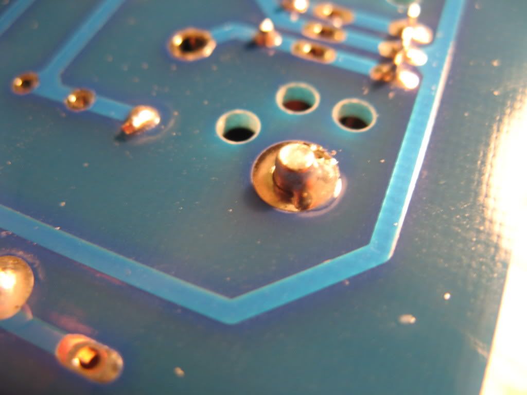
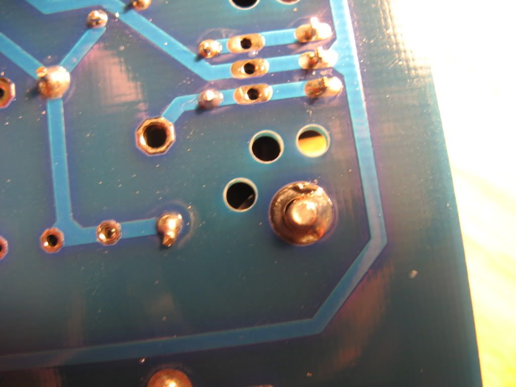
I tack my heatsinks in place like this:

IMG_1995.jpg

IMG_1994.jpg


It takes the strain off the to220 part, but the heatsink is still easily removable.
Just heat up that ribbon of solder and use a solder pump to suck it away.

Also, that solder tack is surprising strong. Chances are you'd crack the board before breaking that joint.
 
Feb 13, 2009 at 3:42 AM Post #981 of 1,948
cool. sounds like a plan.

I was going to do it just like you did.

still, I think if I was paying attention, I would have ordered the screw style instead. solder type is more for automated wave-soldering machines, isn't it? diy is not quite the same and so screws would have been a better choice for the 'oops' that often happen on a one-off assembly we do at home.
 
Feb 13, 2009 at 2:01 PM Post #984 of 1,948
Quote:

Originally Posted by linuxworks /img/forum/go_quote.gif
cool. sounds like a plan.

I was going to do it just like you did.

still, I think if I was paying attention, I would have ordered the screw style instead. solder type is more for automated wave-soldering machines, isn't it? diy is not quite the same and so screws would have been a better choice for the 'oops' that often happen on a one-off assembly we do at home.


Is everything supposed to be for wave-soldering?
wink.gif
wink.gif
I don't think so. Yes, pinned heat sinks are difficult to remove ... but then again, they're not supposed to be removed, anyway. There are issues with tapped heat sinks, too. The pinned heat sinks were chosen on purpose and have served well for several hundred MAXes and MiniMAXes. However, it's DIY and you're welcome to choose the parts you wish at any time, of course.
smily_headphones1.gif


EDIT: If you go back far enough in the history, the M3 was purposely chosen for pinned heat sinks, too - the non-pinned heat sinks were considered an issue in the early days. Pinned sinks are simpler, require less skill to install properly, are more plentiful, and cheaper.

rds's method seems a simple solution if you're afraid of soldering the heat sinks in permanently.
 
Feb 13, 2009 at 2:21 PM Post #985 of 1,948
I'm curious, what is the drawback with the screw type?

is it the need for tapping or that tapping could be off-center?

I don't have taps/dies but a strong screw seems to be all I need to start some threads, as long as the screw is stronger than the heatsink material. or use sheet metal screws, maybe.

I realize that normally you don't have to remove them once you install them, but what if you blow a part that needs replacing? it just seems from a serviceability POV, the more things you can easily and non-destructively remove - the better.

at the least, I would suggest a note in the bom to give the user a choice. it really is worth mentioning and giving alternate part #'s for the screw type.
 
Feb 13, 2009 at 8:17 PM Post #986 of 1,948
has anyone tried these things? they are called 'slow color change leds':

rgb.jpg


on ebay, you search for 'slow color change led' and this comes up.

I have one in a usb xmas tree gadget; it cycles between R,G,B and shades between them. slow transition (hence the 'slow color change' name).

I'm thinking of trying it under the tube sockets. is that going too far?
wink.gif
wink.gif


I did place an order so I'll find out anyway. apparently the controllers and 3 separate led's are in the led casing so you only supply 3v or so to them and they cycle on their own between the various colors. kinda neat in a bling kinda way
wink.gif
 
Feb 13, 2009 at 9:24 PM Post #987 of 1,948
Interesting, very curious to see how those come out... The only thing that might annoy me is if they change at different speeds so the colors don't match up.

On a side note, is the technology built directly into the LED itself? Or does it use a separate controller to handle the color change?
 
Feb 13, 2009 at 9:28 PM Post #988 of 1,948
Almost forgot to mention. Turns out there is a local anodizing shop about 5 minutes from my house. He can do a black anodize for $4.75, but has a minimum order of $125
smily_headphones1.gif


I asked if he could just maybe throw mine in with someone elses order when they needed a black anodize and he said no.

So it looks like I'm back to FPE only, silver or black.
 
Feb 13, 2009 at 9:46 PM Post #989 of 1,948
I broke a led off my usb xmas tree (lol) and its JUST a single led with 'guts' inside. I'll take a photo later on. you can see the 3 led 'bases' and the controller chip (I think) inside.

its JUST 2 wires and you have no control over timing. most likely they each will have a mind of their own. it may not be what people want..

I might go back to using discrete leds or 4wire leds (3 colors but no 'chip'). that way I really can parallel the 2 leds and have the colors be 100% in sync. problem then is to find a simple/cheap outboard controller to PWM control the voltages (3 of them) to the leds and create a nice pattern
wink.gif
I've seen PIC chip circuits do this but its more effort than I'm onboard for.
 
Feb 14, 2009 at 6:56 AM Post #990 of 1,948
So i'm tossing around the idea of making an acrylic sandwich of the faceplate.

Anodized Aluminum with the Logo and Volume Knob cut out ---> Brushed/Frosted acrylic in the middle ---> solid piece of aluminum on the back with holes cut for the LED's to shine though.

Ideally, the strategically placed LED's would light up the Acrylic from the back, and the holes on the front would allow it to glow from behind. Primarily through the logo and around the volume knob.
 

Users who are viewing this thread

Back
Top