Well, Tomb is probably getting annoyed from all the e-mails, but the answers have been very helpful. This is my first DIY project and my first soldering project so don't laugh too hard.
I broke one of the tube sockets so I'm waiting for a rush delivery from beezar.
Anyway, just gunna post up some pictures and can you guys tell me what you think?
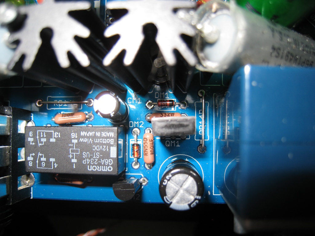
In that last picture if you can see the circle on the image. When I was cutting the excess off a solder i scratched the PCB and a little copper got exposed. Is this a problem? What should I use to fix it?
Thank you for all your help and thanks again to Tomb and Cetoole for a great amp and great support!
Don't worry about the scratch - as long as the trace isn't damaged. I scratch them all the time. The blue mask is not there to provide insulation, only to help control where the solder goes.
It looks OK, except:
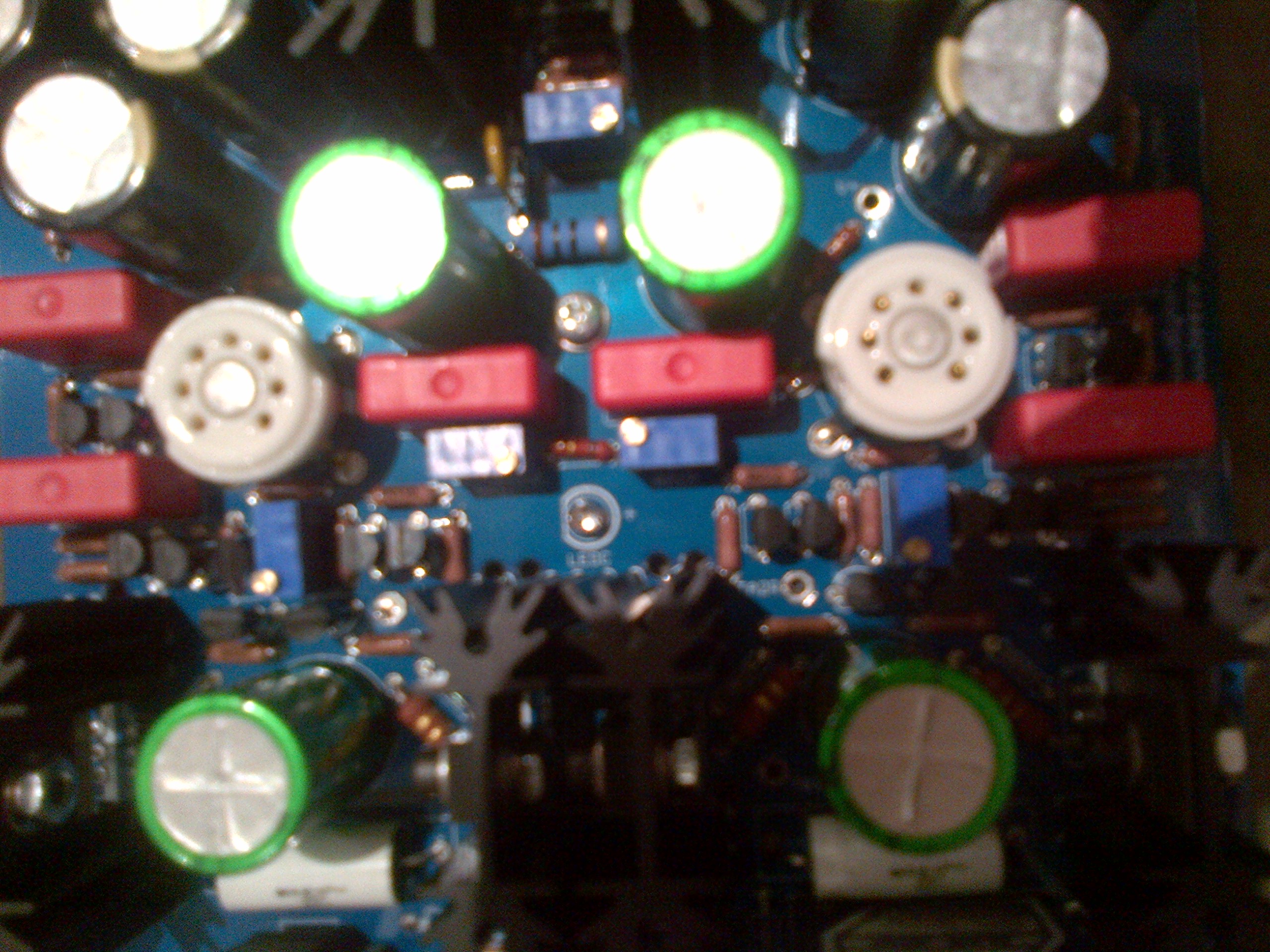
1. It could just be the lighting in the photos, but QB2R appears to be reversed.
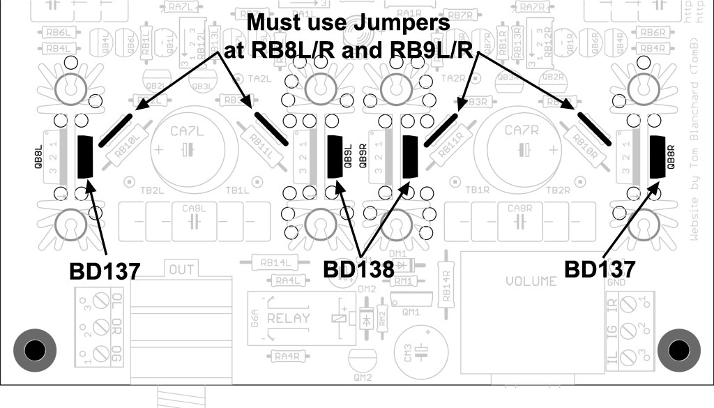
2. Don't forget to solder jumpers at RB8L/R and RB9L/R.
Originally Posted by tomb /img/forum/go_quote.gif Don't worry about the scratch - as long as the trace isn't damaged. I scratch them all the time. The blue mask is not there to provide insulation, only to help control where the solder goes.
It looks OK, except:
1. It could just be the lighting in the photos, but QB2R appears to be reversed.
2. Don't forget to solder jumpers at RB8L/R and RB9L/R.
Wow good eye tom it is reversed.
Speaking of those I had a question. You matched the HFE on the 87s. However, I thought I had to use all the 87s you sent (apparently I needed 6, but got 10). Anyway on one set I checked the HFE and paired a 440 set and installed on the left and right channel QB4. All the others 87s installed were 470s. Will this make a difference?
PS. I ordered some parts from beezar early this morning, can you cancel order 1156? 1157 is the proper order. Thank you
Originally Posted by Coupe /img/forum/go_quote.gif Wow good eye tom it is reversed.
Speaking of those I had a question. You matched the HFE on the 87s. However, I thought I had to use all the 87s you sent (apparently I needed 6, but got 10). Anyway on one set I checked the HFE and paired a 440 set and installed on the left and right channel QB4. All the others 87s installed were 470s. Will this make a difference?
No, it won't make a difference per se, but I thought we went over this in e-mails. It sounds like you're forgeting the four CCS transistors - QA1L/R and QA2L/R. Those are the other four 2N5087's and are in the little bag marked "CCS." Maybe this link will help make it clearer: Millett Hybrid MiniMAX CCS
It's actually more critical that these be well-matched than the ones in the buffer; the performance of the tubes depend on it.
As for the diamond buffer, there are six 2N5087's and six 2N5088's, no more, no less. The PN4392's - one per channel - are in there to set the current bias in the buffer. Quote:
PS. I ordered some parts from beezar early this morning, can you cancel order 1156? 1157 is the proper order. Thank you
I can't get to it while at my day job. Plus, you should send me a PM - it's not appropriate to discuss business orders within a forum thread. No harm, hopefully, I'm sure you weren't aware of the rules around here.
Originally Posted by tomb /img/forum/go_quote.gif No, it won't make a difference per se, but I thought we went over this in e-mails. It sounds like you're forgeting the four CCS transistors - QA1L/R and QA2L/R. Those are the other four 2N5087's and are in the little bag marked "CCS." Maybe this link will help make it clearer: Millett Hybrid MiniMAX CCS
It's actually more critical that these be well-matched than the ones in the buffer; the performance of the tubes depend on it.
As for the diamond buffer, there are six 2N5087's and six 2N5088's, no more, no less. The PN4392's - one per channel - are in there to set the current bias in the buffer.I can't get to it while at my day job. Plus, you should send me a PM - it's not appropriate to discuss business orders within a forum thread. No harm, hopefully, I'm sure you weren't aware of the rules around here.
AHH I see. So the QA1 and 2 are the most important?
Hrm well the 4 87s I have left are 445, 447, 465, 467. Damnit I messed up again. Would these be fine if I matched them L/R with similar HFE or should I just order matching ones from beezar?
Originally Posted by Coupe /img/forum/go_quote.gif AHH I see. So the QA1 and 2 are the most important?
Hrm well the 4 87s I have left are 445, 447, 465, 467. Damnit I messed up again. Would these be fine if I matched them L/R with similar HFE or should I just order matching ones from beezar?
Those are all close enough. Put the 445 and 447 together on one channel, then the 465 and 467 on the other channel.
Actually, it's really not that critical. What's important is that you not have something like a 300 or 500 in that mix.
Originally Posted by Coupe /img/forum/go_quote.gif <snip>
BTW are vacuum tubes like halogen bulbs where you can't touch the glass with your bare finger?
No, but your bare fingers aren't going to feel very comfortable for long if the tube is on.
I am curious as to the trimmers. I gave the DB trims 20 turns till clicks and the other trimmers about 10 turns clockwise. Should I bring them all the way down so I don't burn something when I first fire it up?? I read the diyguide and I just want to verify things before the initial fire up.
Since the amp won't fly. Need to verify!
edit:
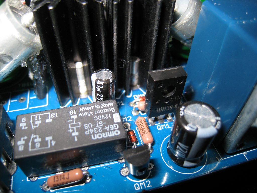
So been verifying. What is the green rectangle by the voltage regulator and does direction matter?
The build has Elna Cerafine and Nichicon ES. I skip the output resistors for better dynamic. Each tube is biased at 14.5V at first and after 2 hours, it dropped to ~13.5V.
Only minor problem is that when I used too much strength to push the tube socket down and broke the tube LED
Now only one side lights up. If anyone could help me desolder the tube socket and LED, please let me know. I really suck at desoldering stuffs.
tube sockets are impossible to remove, i got my the sockets on my ss beta board wonky couldnt remove them. maybe my soldering skills are crap but im sure its hard
Originally Posted by Lil' Knight /img/forum/go_quote.gif If anyone could help me desolder the tube socket and LED, please let me know. I really suck at desoldering stuffs.
Quote:
Originally Posted by Yaka /img/forum/go_quote.gif tube sockets are impossible to remove, i got my the sockets on my ss beta board wonky couldnt remove them. maybe my soldering skills are crap but im sure its hard
I concur with yaka - removing the tube sockets will be all but impossible. A better strategy would be cut power to the second LED to make it look 'balanced' again.
If you really want the tubes illuminated, you could short both LEDs under the tubes and install a second set of LED directly series with RA5 L/R.
This site uses cookies to help personalise content, tailor your experience and to keep you logged in if you register.
By continuing to use this site, you are consenting to our use of cookies.