New Millett Hybrid Maxed Amp
Mar 3, 2009 at 11:12 PM Post #5,671 of 6,727
You could try reflowing solder at all of your critical points, being cautious not to get solder bridges to the ground plane from the top. Good Luck!
 
Mar 4, 2009 at 3:53 PM Post #5,672 of 6,727
people,
i realize that 70% of Millett max í of tangentsoft,. Psu is step, Buffer is of M^3, only input stage is new.
I can't find millett tube in my country(12AE6- 12FM6...) so can i design input stage with another tube such as 12AU7 or 12AX7 ,.....
Please help me, thank.
 
Mar 4, 2009 at 3:54 PM Post #5,673 of 6,727
people,
i realize that 70% of Millett max í of tangentsoft,. Psu is step, Buffer is of PPAv2(mistaken), only input stage is new.
I can't find millett tube in my country(12AE6- 12FM6...) so can i design input stage with another tube such as 12AU7 or 12AX7 ,.....
Please help me, thank.
 
Mar 4, 2009 at 4:23 PM Post #5,674 of 6,727
Quote:

Originally Posted by Mr.Unknown /img/forum/go_quote.gif
people,
i realize that 70% of Millett max í of tangentsoft,. Psu is step,


Nope. The power supply has been totally re-designed, based loosely on the LM317 datasheet. So, it's not really similar anymore. Besides, even Tangent allowed that the design was his PCB layout - not the circuit. The circuit has always been a derivative of the LM317 datasheet. Only now, the power supply has been greatly enhanced. It includes specific measures that work only for the MAX to achieve a very competitive low-noise output - developed through our own exhaustive trial and error experimentation.
wink.gif

Quote:

Buffer is of M^3, only input stage is new.


This is totally incorrect, too. The MAX's buffer was never based on the M3, even with the MOSFET option. It traces its lineage most directly back to Steinchen's implementation of the diamond buffer for the Millett Hybrid. Before that, it was implemented in any number of places, most notably by PPL in the second version of the PPA. However, the diamond buffer is fairly common in its basic circuit and can probably be traced back to some of Walt Jung's designs. The MOSFET version of the diamond buffer has a few extra wrinkles that AMB helped develop, but even then - not based on the M3.

The input stage is pure Pete Millett and has not changed (except a slightly different cetoole-designed-CCS) since his original publication in AudioXpress magazine.
Quote:

I can't find millett tube in my country(12AE6- 12FM6...) so can i design input stage with another tube such as 12AU7 or 12AX7 ,.....
Please help me, thank.


Sorry. Those two tubes you mention are not even close. However, it's not like Millett tubes are scarce. Except for the 12FM6, you can find Millett tubes at just about every vendor who sells tubes, including e-bay, beezar.com, and many overseas outlets.
wink.gif
 
Mar 8, 2009 at 10:13 AM Post #5,675 of 6,727
Hi guys, need some help/advice on my millet. i was playing around with tube rolling the past 2 days and was about to case back my millet when i noticed this(see pictures).

it look burned out and i have no idea what that is suppose to be or do. (i bought the millet and didnt build it myself so i have no clue on the schematics involved)

i didnt dare to turn on my millet after discovering this but my millet was working fine and my headphones werent damaged prior to my discovery.

35kir6v.jpg


2ibm4v8.jpg


ndkl51.jpg


is the problem serious?
how does it affect the whole circuitry?
should i refrain from using the millet until the part is replaced?
what could be the cause of this?

thanks. your help is very much appreciated.
 
Mar 8, 2009 at 1:43 PM Post #5,677 of 6,727
Soloz2 is correct, but that resistor looks woefully undersized. The Panel LED shouldn't be pulling that much amperage, but if it was sized with the rest, it would be 10-15ma. At least a 1/2W resistor is needed. Those are usually twice the physical size of the one in the photo.

EDIT: The tube LED resistors look adequate size, but someone may have assumed that the panel LED wouldn't pull as much and sized it for the same ohms, but less power. If so, it would still pull the same milliamps and burn out.
 
Mar 8, 2009 at 1:56 PM Post #5,678 of 6,727
Quote:

Originally Posted by soloz2 /img/forum/go_quote.gif
that's just RLED. see if the power LED (and tube LEDs) light up if you flip on the power. It likely needs to be replaced.


Quote:

Originally Posted by tomb /img/forum/go_quote.gif
Soloz2 is correct, but that resistor looks woefully undersized. The Panel LED shouldn't be pulling that much amperage, but if it was sized with the rest, it would be 10-15ma. At least a 1/2W resistor is needed. Those are usually twice the physical size of the one in the photo.

EDIT: The tube LED resistors look adequate size, but someone may have assumed that the panel LED wouldn't pull as much and sized it for the same ohms, but less power. If so, it would still pull the same milliamps and burn out.


thanks for the fast replies.

tried powering on and both the power led and tube led lights up.
confused_face_2.gif


is there any danger to my millet if i continue to use it with the burned resistor?

what is the part that i should get to replace it?

thanks for the help.
 
Mar 8, 2009 at 5:01 PM Post #5,680 of 6,727
Quote:

Originally Posted by nocturnalsheet /img/forum/go_quote.gif
thanks for the fast replies.

tried powering on and both the power led and tube led lights up.
confused_face_2.gif


That may be true, but it's probably hanging by a thread. You can count on it failing soon, most likely.

Quote:

is there any danger to my millet if i continue to use it with the burned resistor?


No.

Quote:

what is the part that i should get to replace it?


Soloz2 gave you a good link.

Quote:

thanks for the help.


One other thing - I don't like seeing the center support not used. That's the open hole in the middle. It should be attached to the bottom of the case with a standoff such that the board doesn't flex at all when plugging and unplugging tubes. I guess if you never do any tube-rolling, it'll be fine, but otherwise - something else to work on to keep another failure from occurring that would be much more serious.

Another option is to simply install a screw long enough to touch the bottom of the case. IOW, you'd use a nut to fasten it to the board, but if it was long enough to touch bottom, then it would provide the needed support at least in one direction.
 
Mar 9, 2009 at 3:16 PM Post #5,681 of 6,727
Quote:

Originally Posted by tomb /img/forum/go_quote.gif
That may be true, but it's probably hanging by a thread. You can count on it failing soon, most likely.

No.

Soloz2 gave you a good link.

One other thing - I don't like seeing the center support not used. That's the open hole in the middle. It should be attached to the bottom of the case with a standoff such that the board doesn't flex at all when plugging and unplugging tubes. I guess if you never do any tube-rolling, it'll be fine, but otherwise - something else to work on to keep another failure from occurring that would be much more serious.

Another option is to simply install a screw long enough to touch the bottom of the case. IOW, you'd use a nut to fasten it to the board, but if it was long enough to touch bottom, then it would provide the needed support at least in one direction.


thanks for the advice tomb, in the process of rectifying my millet and sourcing the resistor locally.

@Soloz2 thanks for the link, allowed me to know what exact part to get.
normal_smile .gif
 
Apr 13, 2009 at 8:22 PM Post #5,682 of 6,727
Finally getting round to finishing my millet which i started over a year ago!!!
redface.gif
redface.gif
redface.gif


Been out of the loop in thinking about what i was going to do with it,
i have realised i am really awkward because i ordered a little toroid with it instead of the wall wart. I ant really see any problems as a wall wart is just a little transformer aint it!

i just want to check that the amp will run ok with this before i go ahead and order my face plates from font panel express.

Cant wait to finally get this finished and see what my k601s will sound like with proper power!

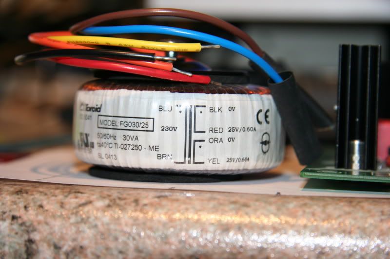
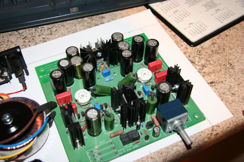
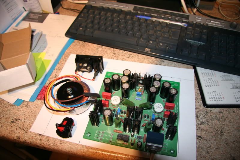
here is a photo the toriod, my board and the general layout of the casing i am thinking about

IMG_4808.jpg


IMG_4811.jpg


IMG_4809.jpg


Thanks for the help in advance guys!

Wana get this build finished finally!
regular_smile .gif
regular_smile .gif
 
Apr 13, 2009 at 10:40 PM Post #5,683 of 6,727
It looks OK from here! Be sure you wire the secondaries of that toroid in parallel - Black and Orange (0V) should be wired together as one lead, then Red and Yellow (25VAC) should be wired together to form the second lead. This will give you 25VAC at 1.2A.

I'd still try to connect it up temporarily and make certain everything works before purchasing the expensive panels. There always a chance the tubes can pick up the interference from the toroid in one position or another. Most likely, it will be fine, but you never know ... hate to spend all that money and then decide the toroid works better in the back or something.
 
Apr 13, 2009 at 11:26 PM Post #5,684 of 6,727
was thinking that about the parallel, school physics coming back to me!

i think ill give the wire up a go tomorrow. and give the thing a listen.

Would i need to fuse the board or will the fuse in the power supply be enough?

any idea what fuse i would need for either of these??

cheers tomb
 
Apr 13, 2009 at 11:26 PM Post #5,685 of 6,727
If there is any way you can fab or source a cover or at least isolate the toroid, it will help.

FWIW, a few others are already using 50VA or 100VA toroids with no issues. I'll be using a 100VA in a NABU where it is isolated from the MAX board.
 

Users who are viewing this thread

Back
Top