New Millett Hybrid Maxed Amp
Jan 28, 2009 at 6:58 AM Post #5,611 of 6,727
To burn up a 2W 2.2 ohm resistor you'll need huge current. I don't see how accidentally biasing a little high is going to make that happen.
It seems there must be something else going on here. Maybe check the resistors at the base...
 
Jan 28, 2009 at 3:23 PM Post #5,614 of 6,727
Quote:

Originally Posted by nocturnalsheet /img/forum/go_quote.gif
anybody did any review/comparisons on the sound differences between say different brands of the same tube(12ae6a,12fm6, 12fk6)?

cant seem to find any info. gotten a millet, thinking of reading up on tubes before i take the plunge.

thanks for the help

regards.


I've sort of given up trying to assign sound qualities per brand.
wink.gif
First of all, the brands were freely mixed from one mfr to another. Even so, I've found great sounding tubes from each of the manufacturers - Tung Sol, GE, RCA, and Sylvania. What distinguishes one from the other is the level of clear highs that are available.

Sylvania generally built the best structure in the tubes - all of them have a channel going across the plates at the top mica spacer. None of the other mfrs used that construction. At the same time, that doesn't necessarily guarantee the best sound.

Generally speaking (very generally) ... and this is per MFR, not painted-on "brand":
RCA - very good overall neutral sound, sort of clear, but slightly soft highs - similar to the BUF634 sound of a PIMETA, if you've heard that. They are very forgiving for almost any recording.
GE - lots of prat, great bass impact and powerful punch, great mids, not as good in the highs as an overall average compared to the others.
Tung Sol - very similar to the RCA's, very neutral, but with "sweeter" extended highs, compared to the RCA's soft highs.
Sylvania - similar to the others - if you find a good one, the highs are very revealing, which can be good or bad, depending on the recording.

All that said, there is much more difference in the sound from type to type: 12AE6 compared to 12FM6 and 12FK6. The 12AE6 has the most impact and is the most dynamic. I would recommend them for high impedance phones in every case.
12FK6 has the best highs and detail, but impact can be lacking except on low impedance phones.
12FM6 is in the middle of the other two.

Despite all of this, you'd be better off deciding on which tube type and making sure you have a decent match in construction and output. As noted, the brand name means nothing.

Hope that helps ...
 
Jan 28, 2009 at 3:47 PM Post #5,615 of 6,727
Quote:

Originally Posted by tomb /img/forum/go_quote.gif
I've sort of given up trying to assign sound qualities per brand.
wink.gif
First of all, the brands were freely mixed from one mfr to another. Even so, I've found great sounding tubes from each of the manufacturers - Tung Sol, GE, RCA, and Sylvania. What distinguishes one from the other is the level of clear highs that are available.

Sylvania generally built the best structure in the tubes - all of them have a channel going across the plates at the top mica spacer. None of the other mfrs used that construction. At the same time, that doesn't necessarily guarantee the best sound.

Generally speaking (very generally) ... and this is per MFR, not painted-on "brand":
RCA - very good overall neutral sound, sort of clear, but slightly soft highs - similar to the BUF634 sound of a PIMETA, if you've heard that. They are very forgiving for almost any recording.
GE - lots of prat, great bass impact and powerful punch, great mids, not as good in the highs as an overall average compared to the others.
Tung Sol - very similar to the RCA's, very neutral, but with "sweeter" extended highs, compared to the RCA's soft highs.
Sylvania - similar to the others - if you find a good one, the highs are very revealing, which can be good or bad, depending on the recording.

All that said, there is much more difference in the sound from type to type: 12AE6 compared to 12FM6 and 12FK6. The 12AE6 has the most impact and is the most dynamic. I would recommend them for high impedance phones in every case.
12FK6 has the best highs and detail, but impact can be lacking except on low impedance phones.
12FM6 is in the middle of the other two.

Despite all of this, you'd be better off deciding on which tube type and making sure you have a decent match in construction and output. As noted, the brand name means nothing.

Hope that helps ...


hi tomb,

thanks for the insightful post. guess i will be trying out different brands of 12ae6a tubes as i am using the hd580 with it. tung sol tubes sounds interesting(that is if i can get my hands on some)

regards.
 
Jan 30, 2009 at 4:15 AM Post #5,617 of 6,727
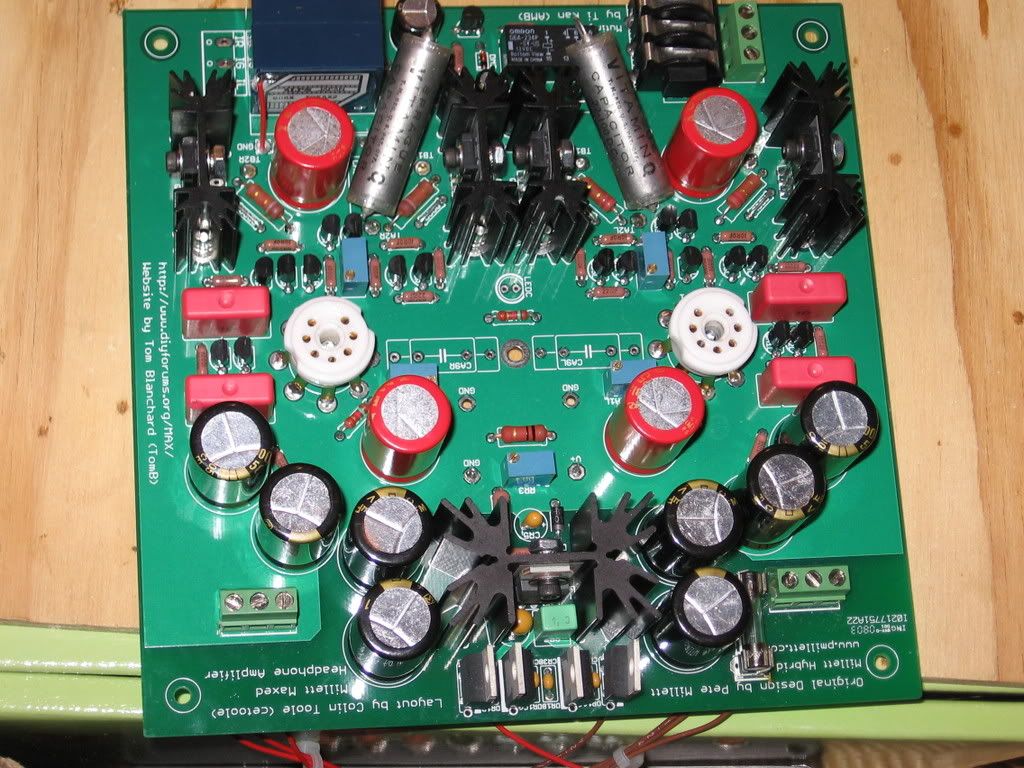
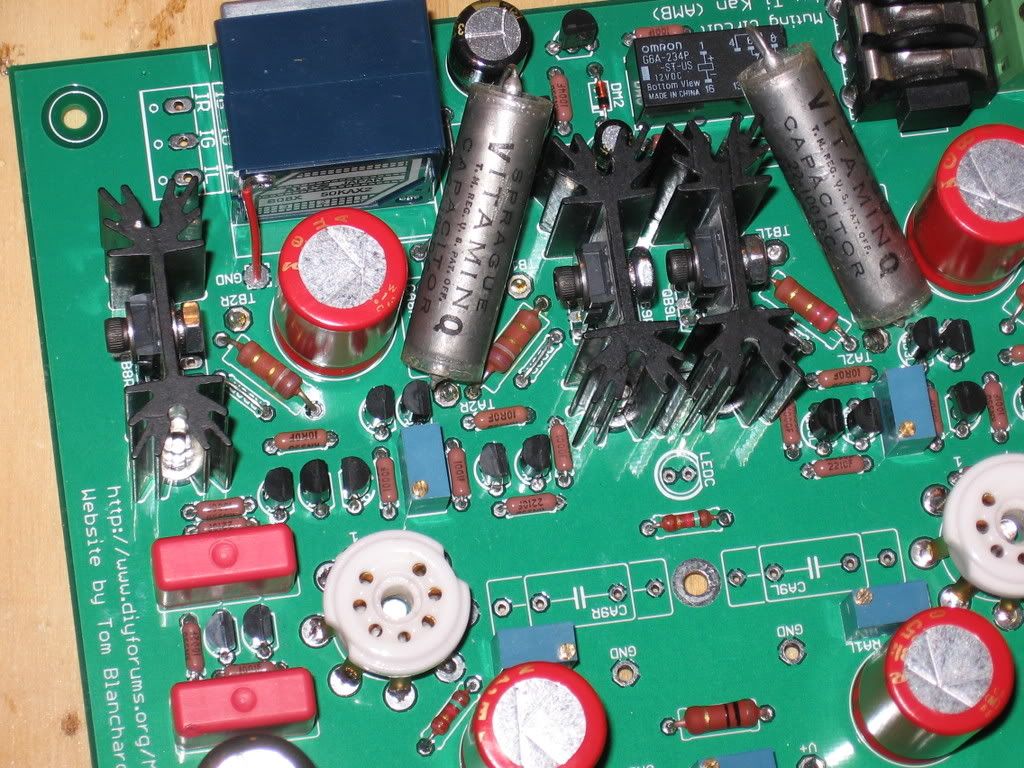
Wow, you can really see the scorching. I would just replace all the transistors in that section and at least RB10/11. Maybe see if you can measure the other resistors, but I would imagine they are all fine. Is that more scorching around the fuse, or just flux? Also, I see you have test points for the buffer bias. Any chance someone ever shorted the buffer bias points?
 
Jan 30, 2009 at 4:27 AM Post #5,618 of 6,727
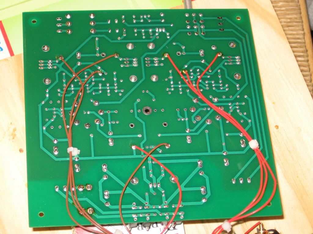
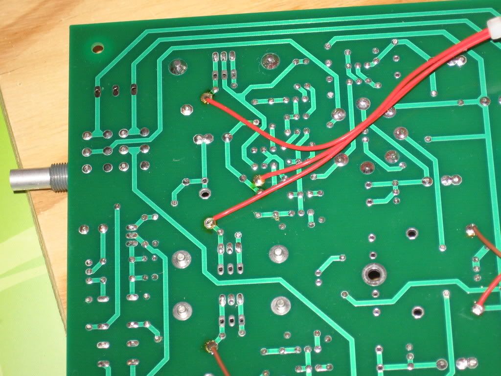
that's just flux around the fuse clips. I actually didn't clean the flux after soldering the wires for the test points. But ya, it definitely looks like the solder joints at RB10/11 had been melted from the heat of the resistors(obviously, if they start glowing bright orange shortly after power-on)...maybe a little on the joints immediately adjacent too

This one shows it a little more clearly
IMG_1095.jpg
 
Jan 30, 2009 at 5:26 AM Post #5,619 of 6,727
I'm like Colin - I would suspect something in the wiring and the case - especially if it happened after you put the lid back on. Maybe the VitQ's are contacting the case lid - or some wiring is getting jammed into the endplate/lid/case fastening points?

I had a nasty scare once where I discovered that I had one of the tipjack wires get stuck in the bottom slot where one of the endplate screws went in. I ended up screwing the screw through the wire's insulation and shorted it out. It could've been real nasty had I let it go for awhile.

I don't see anything wrong in the pics unless the VitQ's have moved and have their leads touching something. It almost appears as if the back lead on one the VitQ's either contacted the nearby test point or the RB10 resistor lead, but it could be the angle of the photo. There's also an exposed lead on the RCA jack? Could that have contacted something?
 
Jan 30, 2009 at 6:17 PM Post #5,620 of 6,727
Quote:

Originally Posted by cetoole /img/forum/go_quote.gif
Any chance someone ever shorted the buffer bias points?


could that happen if you had the DMM probes in the tip jacks and were to switch thru the different modes on the centech DMM (with both the amp and meter turned on)? If so, that may be it. I didn't even think to warn him against that. I did have him checking the tube bias

Quote:

Originally Posted by tomb /img/forum/go_quote.gif
I'm like Colin - I would suspect something in the wiring and the case - especially if it happened after you put the lid back on. Maybe the VitQ's are contacting the case lid - or some wiring is getting jammed into the endplate/lid/case fastening points?


Yaa I was kind of afraid of that when I saw the way a couple of the wires looked as if they had been pinched or kinked. Even if it wasn't that, I prob should have put heat shrink over the exposed metal ends of the tip jacks and shorten a couple of those wires. I don't think it was the VitQs touching the case, as they're well below the top, plus if any part of them were to touch the case it'd just be the tape and the outside metal shell, not the lead

Quote:

Originally Posted by tomb /img/forum/go_quote.gif
I don't see anything wrong in the pics unless the VitQ's have moved and have their leads touching something. It almost appears as if the back lead on one the VitQ's either contacted the nearby test point or the RB10 resistor lead, but it could be the angle of the photo.


nah, the leads would almost have to have been strained to the point of breaking before it touched anything metal that it shouldn't be touching. And ya, that's just a bad angle on the pic.

Quote:

Originally Posted by tomb /img/forum/go_quote.gif
There's also an exposed lead on the RCA jack? Could that have contacted something?


hmm I doubt it at the place you're talking about...but when I got the amp back, the input ground and one of the channels' + wires were loose from the terminal block. I assumed this was from the return shipping, but if it happened on the first shipping (to the buyer) and they shorted could this have caused it? Although I guess if this had been the case, neither channel would have been working upon arrival, which definitely wasn't the case..
confused_face(1).gif


anyway, I guess I know what I need to know what to do to fix the damage (and hopefully prevent it from happening again), regardless of what caused it. The two small transistors between the Wimas are in the amp section right? Should I replace those too?
 
Jan 30, 2009 at 7:14 PM Post #5,621 of 6,727
Quote:

Originally Posted by pinkfloyd4ever /img/forum/go_quote.gif
<snip>

anyway, I guess I know what I need to know what to do to fix the damage (and hopefully prevent it from happening again), regardless of what caused it. The two small transistors between the Wimas are in the amp section right? Should I replace those too?


No - they're the CCS's for the tubes. I doubt seriously they were damaged - they just don't see that much current.

Also, I don't think there's much he could do with the meter, unless he was sticking the probes where they weren't supposed to go.
tongue.gif
If it was working before you buttoned it up, most likely it was a case-wire-crushing incident.
 
Feb 4, 2009 at 8:38 PM Post #5,622 of 6,727
I'm wondering about adding a plexi top plate to the standard Hammond case.

It wouldn't be too hard with Front Panel Express...the 2mm thick plexi should still slide in the panel slot. Still, I'd prefer to have a "screw down" top that I could remove without taking off the end plates.

Anyone have an idea how to accomplish this? I have an idea of gluing some kind of screw receptacle into the slots, one at each corner area, that would stick out 1/4" or so and allow you to screw a plate down.

I just don't know where I could find such a part (basically a small bracket with a screw hole on one end). Maybe there's a simple way to make this part? Any ideas appreciated.
 
Feb 5, 2009 at 2:38 AM Post #5,623 of 6,727
Quote:

Originally Posted by slowpogo /img/forum/go_quote.gif
I'm wondering about adding a plexi top plate to the standard Hammond case.

It wouldn't be too hard with Front Panel Express...the 2mm thick plexi should still slide in the panel slot. Still, I'd prefer to have a "screw down" top that I could remove without taking off the end plates.

Anyone have an idea how to accomplish this? I have an idea of gluing some kind of screw receptacle into the slots, one at each corner area, that would stick out 1/4" or so and allow you to screw a plate down.

I just don't know where I could find such a part (basically a small bracket with a screw hole on one end). Maybe there's a simple way to make this part? Any ideas appreciated.


I hope it's more than 2mm thick.
wink.gif
EDIT: Never mind - 2mm will be fine - don't know what I was thinking.
wink.gif


As for a screw down top plate, I don't know. The problem is that the top slot in the Hammond is not the most stable thing to attach to, unless you do it along the entire length. Amb does most of his cases this way, I think - by attaching the screw posts to the acrylic, then there are tab(s) that slide into the case slots (I think). However, I don't think the assembly would be stable if you unscrewed the mounts from the top plate - they would just fall out of the slot.

It might be worth sending him a PM or e-mail and asking him how he does it, though.
 
Feb 9, 2009 at 3:42 AM Post #5,624 of 6,727
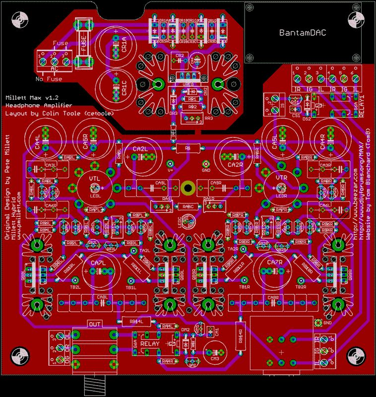
cetoole has finished the design on the MAX V1.2:

MAXv1.2a.gif


Here's the schematic, too (click for a larger image):


Of course, the primary changes are the incorporation of the superior MiniMAX power supply, and room for the BantamDAC on board. Switching between BantamDAC and "normal" RCA inputs will be controlled with a back panel SPST switch (2-position terminal block) that throws a 24V relay. Since the 24V relay was required because of the limited space back there, we also incorporated it into the headphone delay-relay.

Surprise, surprise! With fewer parts and higher voltage, the headphone relay-delay works better than ever. We have sized and tested the parts selection for a Cold-Start delay time of 45 seconds, but the Hot-Start time is still ~30 seconds. Transients on cutoff - if they are there - are too fast to measure with my Fluke. This is an improvement over the existing design and other delay-relays, which throw a few volts of transient offset upon shutoff. Normally, this is trivial with a connected load and only noticeable when measured in a zero-load condition. However, this new circuit appears to have no offset on shut-off at all, load or not. This is of course, a nice benefit to the new circuit, besides the commonality of relays and fewer parts. I have been living with the new relay circuit on a MiniMAX for a few weeks now with no ill effects whatsoever - as stated it works better.

As mentioned to some other people on different occasions, there's little to do to improve the existing MiniMAX with BJT's - this design is not going to do any better, and the MiniMAX package with the custom case is unbeatable. However, the regular MAX board always allowed for 1-1/2" sinks and parts, so MOSFETs should work well. Accordingly, we are going to steer the focus for the MAX V1.2 in that direction of MOSFETs, but of course, it can always be built with BJT buffers, too.

A request for quote on prototypes has been sent. I don't know if we'll need volunteers, yet. The board is pretty well proven and we've proven the new relay circuits, too. If anything, a proto build will only be necessary to prove out the fit with the case and the BantamDAC hookup. We'll keep you updated.
smily_headphones1.gif
 
Feb 9, 2009 at 1:35 PM Post #5,625 of 6,727
Quote:

Originally Posted by tomb /img/forum/go_quote.gif
cetoole has finished the design on the MAX V1.2:


Of course, the primary changes are the incorporation of the superior MiniMAX power supply, and room for the BantamDAC on board. Switching between BantamDAC and "normal" RCA inputs will be controlled with a back panel SPST switch (2-position terminal block) that throws a 24V relay. Since the 24V relay was required because of the limited space back there, we also incorporated it into the headphone delay-relay.

Surprise, surprise! With fewer parts and higher voltage, the headphone relay-delay works better than ever. We have sized and tested the parts selection for a Cold-Start delay time of 45 seconds, but the Hot-Start time is still ~30 seconds. Transients on cutoff - if they are there - are too fast to measure with my Fluke. This is an improvement over the existing design and other delay-relays, which throw a few volts of transient offset upon shutoff. Normally, this is trivial with a connected load and only noticeable when measured in a zero-load condition. However, this new circuit appears to have no offset on shut-off at all, load or not. This is of course, a nice benefit to the new circuit, besides the commonality of relays and fewer parts. I have been living with the new relay circuit on a MiniMAX for a few weeks now with no ill effects whatsoever - as stated it works better.

As mentioned to some other people on different occasions, there's little to do to improve the existing MiniMAX with BJT's - this design is not going to do any better, and the MiniMAX package with the custom case is unbeatable. However, the regular MAX board always allowed for 1-1/2" sinks and parts, so MOSFETs should work well. Accordingly, we are going to steer the focus for the MAX V1.2 in that direction of MOSFETs, but of course, it can always be built with BJT buffers, too.

A request for quote on prototypes has been sent. I don't know if we'll need volunteers, yet. The board is pretty well proven and we've proven the new relay circuits, too. If anything, a proto build will only be necessary to prove out the fit with the case and the BantamDAC hookup. We'll keep you updated.
smily_headphones1.gif


Yeah! Just let me know when they are ready for sale and put me down for two. I need one for my MOSFET-MAX and I'm so far behind, I'll go ahead and build my BJT integrated amp with the new board and mount the phono stage where the BantamDAC would be for my console.

I have 3 of the current style boards, so I will be building one of those up with BJTs and and probably the Muse ES caps then I can listen to it with the other two and see how much of a difference I can hear.

Also, if anyone wants a current style board, I'll let two of them go for $5 each plus the USPS Priority Mail charges.
 

Users who are viewing this thread

Back
Top