New Millett Hybrid Maxed Amp
Sep 14, 2008 at 5:10 PM Post #5,476 of 6,727
Quote:

Originally Posted by acold7dusta /img/forum/go_quote.gif

I'll get a shot of the DM1 in a bit.


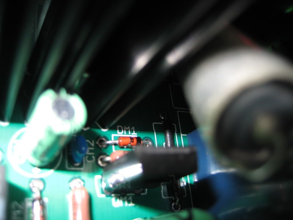
Just make sure the dark band is towards the pot.

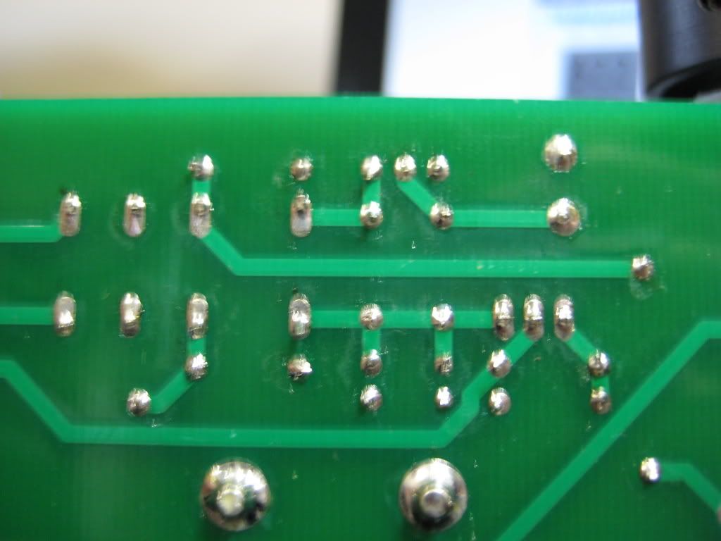
I can't see anything obvious. You probably should follow MrMajestic's advice and reflow the joints and see if something changes...

Edit: Looks like Tom posted at the same time. At least we are in agreement...
 
Sep 14, 2008 at 5:35 PM Post #5,477 of 6,727
IMG_1073.jpg


soldering iron is heating up, so ill be reflowing solder shortly

tomb,
why can't an MPSA14 be used for QM2? It's exactly what was listed in the BOM.
 
Sep 14, 2008 at 6:02 PM Post #5,478 of 6,727
Quote:

Originally Posted by acold7dusta /img/forum/go_quote.gif
tomb,
why can't an MPSA14 be used for QM2? It's exactly what was listed in the BOM.


He meant that one of the problems could be that you are NOT using an MPSA14 for QM2. You are using one, so that not the problem
smily_headphones1.gif
 
Sep 14, 2008 at 6:50 PM Post #5,479 of 6,727
reflowed the solder across the whole board: (sorry about my unsteady arm)

IMG_1079.jpg


much better connections, but still no sound.

Is there any way i can test to see if QM2, QM1, DM1, DM2, and the relay are all working properly?
 
Sep 14, 2008 at 7:09 PM Post #5,480 of 6,727
Reflow the connections from the top, too. The only connection to Ground is through the ground plane on top. (Well, there's through-hole plating, but it's not a good idea to depend on that.) DM1 looks like it's not even connected to the ground plane in one of your pics up there.

You can measure the voltage to Ground of the following parts, but wait for 2-3 minutes before doing it, to be sure that you have given the relay enough time to close.

Refer to this schematic:
e12sch.jpg


It's pretty difficult to measure around the legs of the transistors, so let's measure the resistors and the diodes. Put one probe in a "GND" connection on the board (anywhere - the further away, the better), then use the other probe to measure the following:

RM1 - each leg
DM1 - each leg (note which side has the black stripe)
RM2 - each leg
DM2 - each leg (note which side has the black stripe)
RA4L/R - each leg

Come back and tell us what you get.
smily_headphones1.gif
 
Sep 14, 2008 at 11:56 PM Post #5,481 of 6,727
thanks alot for this feedback!

Tom,

RM1-leg 1=25.6v
leg 2=2.2v
DM1- leg 1= 0v assuming this is a problem...
leg 2 (black stripe)= 2.21v
RM2-leg 1=1.22v
leg 2= 1.63v
DM2- leg 1= .6v
leg 2 (black stripe) = 1.62v
RA4L- 12.8v (assuming it can be measured from TA2L/R)
RA4R- 12.8v
 
Sep 15, 2008 at 12:16 AM Post #5,482 of 6,727
Quote:

Originally Posted by acold7dusta /img/forum/go_quote.gif
thanks alot for this feedback!

Tom,

RM1-leg 1=25.6v


This is essentially V+.
Quote:

leg 2=2.2v


This is the remaining voltage after current flow through RM1. EDIT: This is the problem! You should have 10-12Volts right here. It's probably a Mouser/keyboard error. I bet RM1 is 332K instead of the 3.32K that's required!.
Quote:

DM1- leg 1= 0v assuming this is a problem...


Nope. This leg of DM1 is tied to Ground. You should get 0V.
Quote:

leg 2 (black stripe)= 2.21v


This leg is back to the same point as the leg 2 of RM1 (~2.2V)
Quote:

RM2-leg 1=1.22v


I can't tell which is which here, but this is the problem, combined with leg 2.
Quote:

leg 2= 1.63v


Either this leg or leg 1 of RM2 should be 10-12Volts.
Quote:

DM2- leg 1= .6v


There should be more voltage here.
Quote:

leg 2 (black stripe) = 1.62v


If this is the high side of DM2, it should be 10-12Volts.
Quote:

RA4L- 12.8v (assuming it can be measured from TA2L/R)
RA4R- 12.8v


These aren't really in the delay circuit. They are charging the output caps at 1/2 the supply voltage per channel. So, they are more or less perfect.

EDIT: The problem appears to be that maybe you substituted a 332K resistor for RM1 instead of 3.32K. Those upper legs of RM2 and DM2 should be seeing 10-12 Volts.
 
Sep 15, 2008 at 1:15 AM Post #5,483 of 6,727
hmm i guess ill reflow the solder again on QM2, but it doesnt look promising. Otherwise ill get an order in with mouser tomarrow. Thanks for the help/support again. I really appreciate it
 
Sep 15, 2008 at 4:22 AM Post #5,484 of 6,727
Quote:

Originally Posted by acold7dusta /img/forum/go_quote.gif
hmm i guess ill reflow the solder again on QM2, but it doesnt look promising. Otherwise ill get an order in with mouser tomarrow. Thanks for the help/support again. I really appreciate it


Actually, I made the wrong conclusion. Going over it again and comparing to one of mine, you should have 10-12Volts right there at the end of RM1/DM1.

Looks like you put in a 332K resistor instead of a 3.32K resistor? There's way too much voltage drop after RM1.
 
Sep 15, 2008 at 3:11 PM Post #5,485 of 6,727
Great catch Tom. I took my ohmmeter and got 3.32K on RM2, and 987K on RM1. Simple enough to swap to resistors. Thanks for the walkthrough, I should've checked that stuff day one...


...and it lives!

thanks alot guys!
 
Sep 15, 2008 at 3:15 PM Post #5,486 of 6,727
Quote:

Originally Posted by acold7dusta /img/forum/go_quote.gif
Great catch Tom. I took my ohmmeter and got 3.32K on RM2, and 987K on RM1. Simple enough to swap to resistors. Thanks for the walkthrough, I should've checked that stuff day one...


...and it lives!

thanks alot guys!


Glad to hear it!!
smily_headphones1.gif
 
Sep 15, 2008 at 11:02 PM Post #5,487 of 6,727
acold7dusta, good job! Another Max Lives! :wink: :wink: :wink:

Let us know how it sounds.
 
Sep 16, 2008 at 4:05 PM Post #5,488 of 6,727
sounds great! i love how it sounds-smooth highs, great bass extension and very "airy" sound. Once I complete my LOD for my zune, drill my top panel and wire up my front LED ill be all set!
 
Sep 18, 2008 at 7:40 PM Post #5,489 of 6,727
CAD printouts?

hi guys - can anyone point me to where i might download the cad cutouts for the MAX faceplates and casework? i've had a look on the max website and the cad printouts are mentioned but I can't find a download link!

thanks
 
Sep 18, 2008 at 7:59 PM Post #5,490 of 6,727
Quote:

Originally Posted by Migroo /img/forum/go_quote.gif
CAD printouts?

hi guys - can anyone point me to where i might download the cad cutouts for the MAX faceplates and casework? i've had a look on the max website and the cad printouts are mentioned but I can't find a download link!

thanks


Under Construction -> Drawings & Templates

There are many files to pick from.
smily_headphones1.gif
 

Users who are viewing this thread

Back
Top