New Millett Hybrid Maxed Amp
Nov 10, 2007 at 12:02 AM Post #2,356 of 6,727
Quote:

Originally Posted by kvant /img/forum/go_quote.gif
I don't think this is correct. The bias current only determines, how long the buffer stays in class A. When the voltage swing exceeds certain limit, the buffer switches over to class B, but that does not mean that it clips. BTW, the bias 20mA per transistor in the original buffers actually means 40mA per channel, since there were paralleled output devices. This, in turn, is not that much lower than the general recommendation of 50mA per transistor for MH MAX, that has only one pair of output devices per channel.


Good info! I had posted concerns a couple of months ago, about the possibility of clipping with an overloaded input signal. But didn't realize that the trannies were working the way that you describe. Thanks, very enlightening.
wink.gif
 
Nov 10, 2007 at 12:09 AM Post #2,357 of 6,727
Just burnt out my second tube led.. Did I notice a change to the led resistor ? some way to remedy this from happening more ? Im using ultraviolet leds and not the ultrabright blue ones.
 
Nov 10, 2007 at 3:52 AM Post #2,358 of 6,727
Quote:

Originally Posted by tomb /img/forum/go_quote.gif
What context is this from? As a matter of fact, CCS current is largely arbitrary within a certain range. Pete Millett actually tried a full milliamp (1.0ma) on the original, but said that the result was "slightly higher distortion." The guide for this are the tube curves for the various Millett tubes. Those can be found in the tube data sheets which are on the MAX website under Millett MAX tubes.


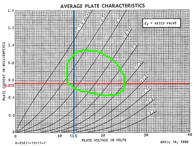
it was in the context of the CCS page on the site, combined with the BOM where it has "Optional selection: Results in CCS current of 0.65 mA" in reference to the alternate values of RA8/9. From the graph on the CCS page and the associated info, I was under the impression that .575 was the ideal CCS current for maximum performance and tube longevity in most cases, and I just guessed that the .65ma was intended for mosfets since they use more current. Quote:

Originally Posted by tomb /img/forum/go_quote.gif
The object is to pick a CCS current point (line) that generally intersects at the linear portion of the tube curves. You don't want to pick a CCS point that's down in the part of the curves that are curved.
wink.gif
Those curves are different for each tube, too. For instance, one might look at the 12AE6 and it might look as if 0.3ma would be sufficient for the CCS. However, look at the 12FM6 curves, and 0.3ma is down in the region where the lines are still currving sharply. So, a higher point is selected, but not too high up around 1ma where Pete noted some distortion.


So, just to make sure, you're saying that anywhere on that I(V) graph is as good as the next as long as it's around the middle of the parts of the curves that are long and straight? EDIT: If you're totally confused by that description (as I prob would be too) the region circled in green:
MAXccs.jpg


Quote:

Originally Posted by tomb /img/forum/go_quote.gif
I built 4 of them and still didn't catch what you had said. Luckily, I can't make the claim of being an EE - just an ignorant ME.
wink.gif
tongue.gif


WORD, me too...well, ME student anyway

Quote:

Originally Posted by Troyhoot /img/forum/go_quote.gif
Just burnt out my second tube led.. Did I notice a change to the led resistor ? some way to remedy this from happening more ? Im using ultraviolet leds and not the ultrabright blue ones.


ooo really, I was gonna do that, didn't think anyone else had. Is it as awesome as I hope it will be, as in like a fluorescent blacklight? Where'd you get your LEDs?
 
Nov 10, 2007 at 5:35 AM Post #2,360 of 6,727
Duplicate post of below.......... V
 
Nov 10, 2007 at 5:57 AM Post #2,361 of 6,727
Quote:

Originally Posted by Troyhoot /img/forum/go_quote.gif
Just burnt out my second tube led.. Did I notice a change to the led resistor ? some way to remedy this from happening more ? Im using ultraviolet leds and not the ultrabright blue ones.


Remember to use caution with UV leds. You can get away with longwave UV, as long as you don't stare at it too long. Shortwave UV, will damage the corneas of your eyeballs however.
blink.gif
wink.gif
 
Nov 10, 2007 at 6:28 AM Post #2,362 of 6,727
Well I finished building my millet max tonight (Big thanks to Jeff for the kit). When I powered it up everything looked good... no smoke, I had the DB bias pots turned all the way clockwise. The problem is, with the pots at their minimum setting I'm still reading 160 mA for the left side and 127 mA for the right side. Does anyone have any ideas what the problem might be?
 
Nov 10, 2007 at 6:52 AM Post #2,363 of 6,727
I figured it out... i had a 243 and 253 transister mixed up. Hope I didn't fry anything.
 
Nov 10, 2007 at 8:00 AM Post #2,364 of 6,727
Quote:

Originally Posted by willisv /img/forum/go_quote.gif
I figured it out... i had a 243 and 253 transister mixed up. Hope I didn't fry anything.


If you can get your system to bias properly now, then you didn't fry anything. Sniff test for burnt plastic and visual for bubbled plastic. If it biases properly give it a listen!
biggrin.gif
 
Nov 10, 2007 at 9:42 AM Post #2,365 of 6,727
Well I'm happy to say that everything is O.K. I got all my settings where their supposed to be and plugged in some headphones for a listen. This amp sounds amazing, I'm very happy with it so far. I think my next step will be to take out the dale vishay resistors at RB14 and see if that improves the sound. I'll post some pics tomorrow, I gotta get some sleep
biggrin.gif
 
Nov 10, 2007 at 10:20 AM Post #2,366 of 6,727
good work willisv, for the built and also for the auto-troubleshooting! Another MAX lives!

The glassjar kit does indeed sound great, doesn't it? Just let it burn in for a while (so the tubes burn their gases and all components settle down a bit)... it really improves with a bit of usage and good biasing of the buffers.
 
Nov 10, 2007 at 10:23 AM Post #2,367 of 6,727
Quote:

Originally Posted by Troyhoot /img/forum/go_quote.gif
Just burnt out my second tube led.. Did I notice a change to the led resistor ? some way to remedy this from happening more ? Im using ultraviolet leds and not the ultrabright blue ones.


Yes, I changed the LED resistors to 2K. It was more a matter of convenience, though - offering a better safety factor for a 2K, 1/2W resistor, which is easier to find.

I'm not sure it's going to help the UV LEDs, though. If you're talking the UVs from LSDiodes, I've burned every one that I ran near the recommded current - all three burned up on the 1st MAX prototype. I asked Vixr if he had the same problem - he uses the UVs often - but no, no problem.

Maybe we're just unlucky. I've never burned out any other LED.
 
Nov 10, 2007 at 10:29 AM Post #2,368 of 6,727
Quote:

Originally Posted by pinkfloyd4ever /img/forum/go_quote.gif
OOO I see, so assuming I'm using a PS voltage of 27V (which I will be), it'd be more accurate to say along the blue line AND inside the green area? So, for whatever tube this graph is for, that'd be somewhere between .4 and .9 mA? Or am I just making sh!t up?


Yes, but there are a couple of facts, mentioned earlier, that you have to roll into your choice of CCS current:

1. Pete has documented that going up as high as 1.0ma caused a noticeable increase in distortion. One can deduce from that the lower values are probably better than the 0.9ma.
2. From the perpspective of the designer, you want to pick something that is able to utilize all three tubes. So, if you pick a number from that graph - it looks like one for a 12AE6 - you should compare it with the graphs from the other tubes and make certain the CCS current is in an acceptable regime.

As noted earlier, numbers around 0.3 or perhaps even 0.4 are not in the linear area of the tube curve for the 12FK6.
 
Nov 10, 2007 at 11:29 AM Post #2,369 of 6,727
[size=xx-small] Quote:

Originally Posted by tomb /img/forum/go_quote.gif
Yes, I changed the LED resistors to 2K. It was more a matter of convenience, though - offering a better safety factor for a 2K, 1/2W resistor, which is easier to find.

I'm not sure it's going to help the UV LEDs, though. If you're talking the UVs from LSDiodes, I've burned every one that I ran near the recommded current - all three burned up on the 1st MAX prototype. I asked Vixr if he had the same problem - he uses the UVs often - but no, no problem.

Maybe we're just unlucky. I've never burned out any other LED.


[/size]

Hmm well if I burn another one out Im going to either change colors or just take them out completly. Might just be an UV thing, or a bad batch this time. The first one I replaced is already dimmer then the one I replaced last night.
 
Nov 10, 2007 at 2:48 PM Post #2,370 of 6,727
Quote:

Originally Posted by Troyhoot /img/forum/go_quote.gif

Hmm well if I burn another one out Im going to either change colors or just take them out completly. Might just be an UV thing, or a bad batch this time. The first one I replaced is already dimmer then the one I replaced last night.


One thing - I have a UV on an Alien DAC from the same batch and it's going strong. However, by my calcs the resistor selection on the Alien puts it down around ~7.5ma. So, I guess they will last if the current is severely reduced. The Alien's not very bright, however - it would be about like a power-on LED if it wasn't transparent and directional. That would make it 3.5Kohms on the MAX to run that same current, but I'm not sure they would be very useful at that - for the panel LED, yes, but nothing great for tube lighting. As you know, the UV's are already way down on the MCD's compared to high output LED's.

You might try a 2K resistor such as on the revised BOM or perhaps a 3K - it may keep them from burning out at any rate.

By the way, the MAX's original LED resistors were sized according to LSDiode's referenced LED calculator. So, there's definitely something weird going on with these UV's.
 

Users who are viewing this thread

Back
Top