Quote:
Originally Posted by babbkutz@comcast /img/forum/go_quote.gif
tomb......2 questions relating to the casework on the MAX site......(1) part used for the mini plug (female) on the front panel?
|
Mouser #
161-7400-EX. Note that this is actually a "commodity" part and is sold under many labels, including Philmore. I've bought many of them at Fry's.
Quote:
| and (2) parts used for the test points on the rear |
Mouser Part #
530-105-0801-1. This one is white, there are different part numbers for other colors. Some may call these cheap - and they are - but they are entirely functional for me, are totally insulated being plastic, and have a crimp/solder connection. Higher quality tip jacks sometimes used by others have one of those p2p studs that has to be wire wrapped - yuck.
I actually bought these in bulk from a local electronics store that was relinqushing their storefront building. I only got the white ones, and then dyed them in the sink with grocery store RIT dye - could've made stripes if I had masked them properly.
Quote:
| .......details on connection to the board........Thanks |
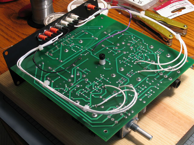
I have been remiss in finishing pics and text on wiring details - I will try to complete that today. If you are referring to the specific wiring for these tip jacks, I simply soldered them into the bottom of the board at all the test positions. The center gray jack is the ground, the voltage adjust jack is off to the side away from the others. Then the first two on either side are the tube bias - L/R. Then DB bias - L/R, A and B. Of course, you simply use the L or R tube bias test point as the reference for the DB test points for L or R, respectively.
Others have remarked that there's not enough room between the jacks for typical DMM test probes, but all you need do is plug in the COM jack all the way into the requisite tip jack. Then, even if the test point jack is immediately adjacent, only a partial insertion is plenty to make a measurement - and to stay in place.
The downside to this is that the tip jacks are soldered to the board, and are installed into the backplate from the outside. This means the backplate is forever attached to the bottom of the board. Accordingly, I built in plenty of slack to remove any issues with ever removing the board, endplate, etc. as necessary:
This pic is on the
MAX website at "Construction -> Casework -> Wiring&Assembly - Pt 3".
EDIT: I actually positioned the tip jacks a little too close to the bottom of the case. The jacks are so close that the nuts match up flat-to-flat. Unfortunately, the nut corners were far enough down that they were touching the bottom of the case and interfered with closing everything up. I sort of forced the nuts into an inbetween position and finally got everything to fit. I think this happened because the metal is quite a bit thicker on the MAX Hammond case compared to smaller Hammond cases - the clearance was that close. I need to adjust the CAD file drawing on the site accordingly, so keep that in mind.