If that's the case I am just confused by the naming from manual. In manual they show 2x DUAL LP (which would be U1 and U2 from schematic for each channel) and then U3 would be I/V that's split between right/left channel?
I am not an expert in audio(I am electronic engineer by trade, but doing mostly digital stuff and C embedded programming) but it would be more logical for me if the split each of DUAL amp for channel.
This way we would have DUAL LP (having U1 for left and right channel), DUAL LP (having U2 for left and right channel), and DUAL I/V same as stated above. This way you have most versatility of switching and also you ensure that both channels will play with same characteristic - even if you put different DUAL opamps in each slot (LP | I/V | LP).
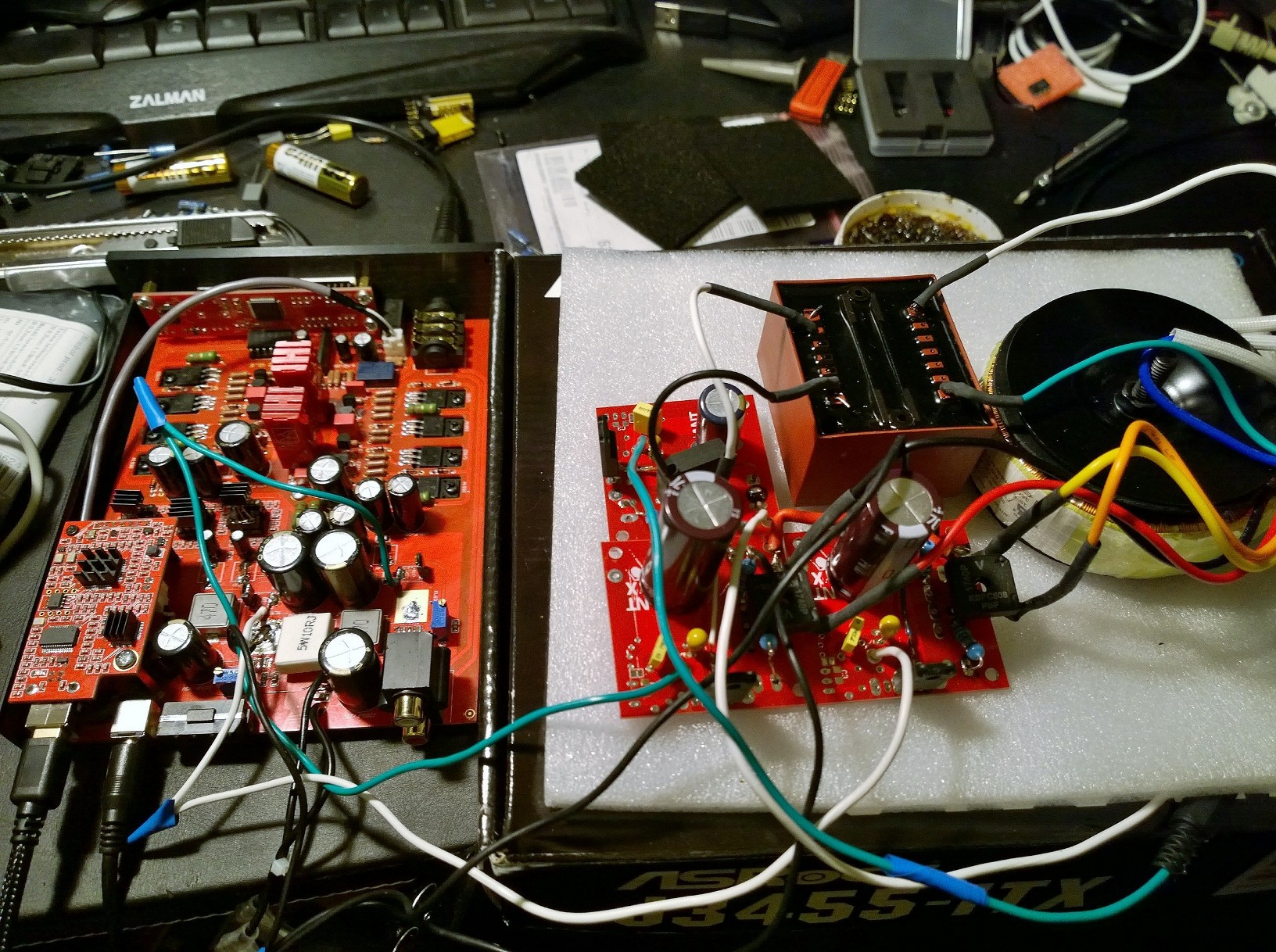
Looking closer on pic you've linked I've seen something concerning.
Soldering like this should never pass QA (assuming board was not modded/resoldered by someone).
Excessive amount of solder causing balls at the end of pins, what is worse even balls
BETWEEN the pins that might couse a short. Could be easily fixed by:
1. Bigger pads on PCB to accomodate solder and also make accesing pins easier (would require PCB change).
2. Stencil correction by making smaller holes for solder to pass through or making whole stencil with thinner metal sheet (easy fix on assembly end - does not require PCB changes).
I know that it does not concern audio, just throwing my 2 cents.
Anyway this flaw could've been coused by someone modding the device or resoldering chip. If it was like that from production it might have been spotted and fixed with new revision


![IMG_20190528_225418[1887].jpg](https://cdn.head-fi.org/a/10307231.jpg)


")


