yzriver
Head-Fier
- Joined
- Jun 20, 2008
- Posts
- 52
- Likes
- 0
Hi all:
I need more eduacation from you.
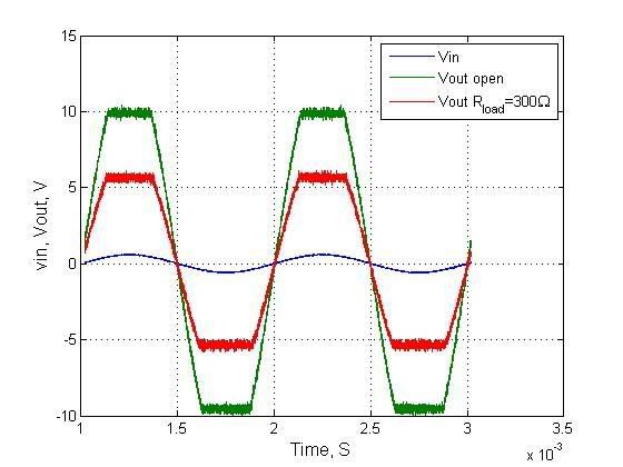
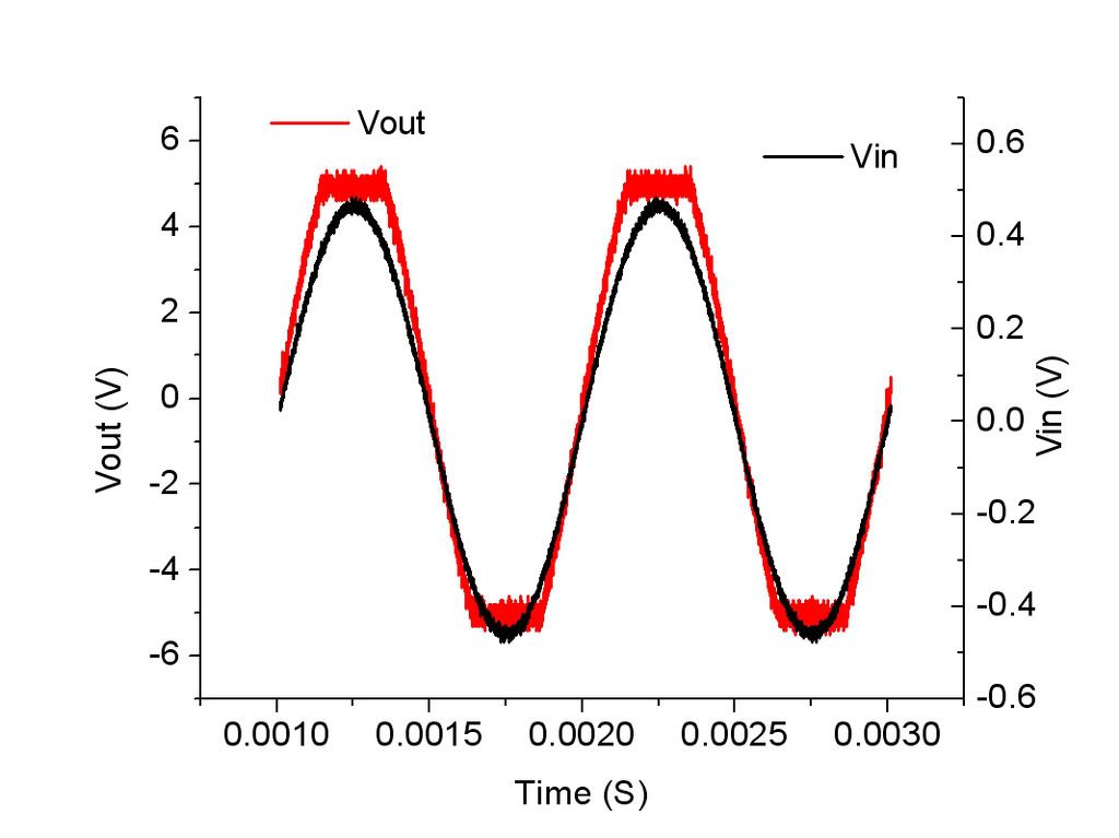
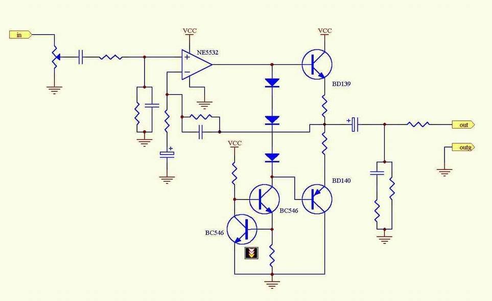
I just measured the Vin Vout of this headphone amp. I don't like the performance of it. I have a 300Ohm resistor as a load at the output. I captured the curve of voltage drop on this resistor. Please look at the curve. Input is 1KHz sin wave.
The output voltage saturates at +-5V, as the red line indicates. What cuases this problem? Is it from the OPA saturation? I have a powerful DC source, 24V 3A, so I don't think it is the problem of DC supply.
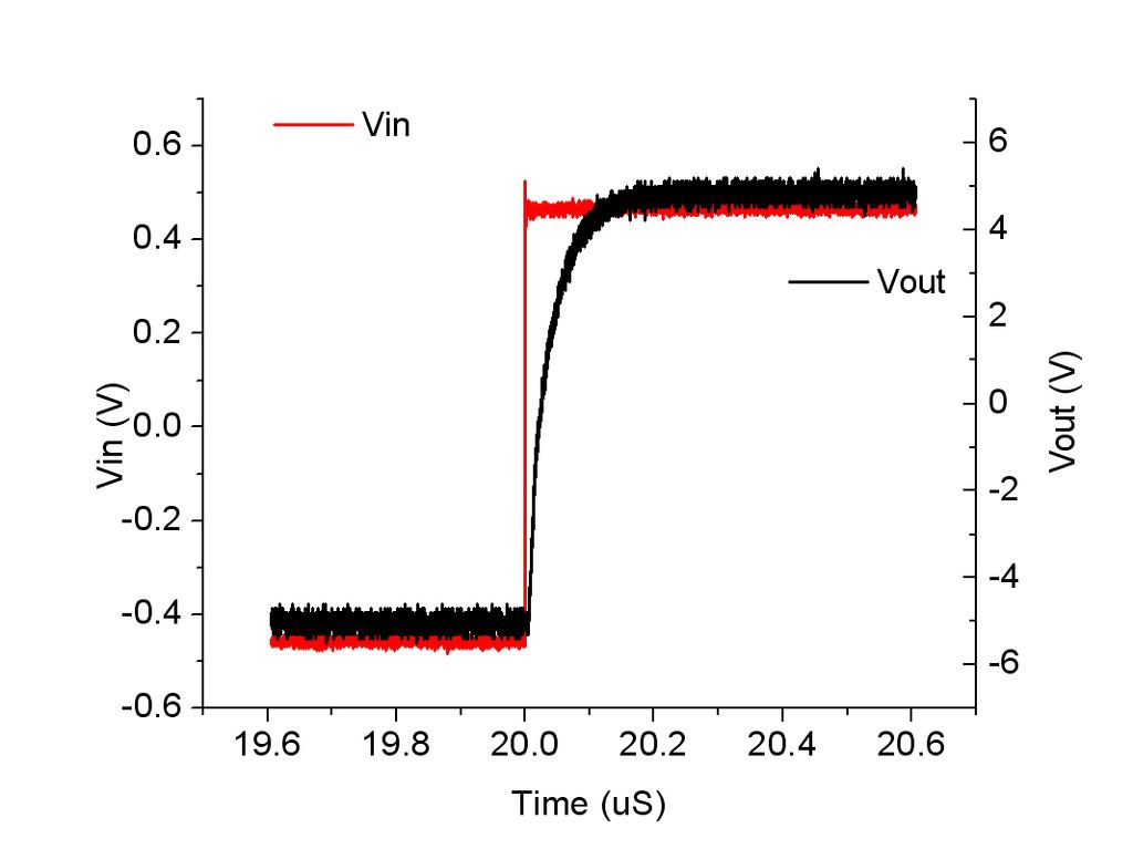
The other problem is that it is pretty slow. It takes 10 nS swich from -5V to 5V. Is it the slew rate 1V/1uS? This number dispoints me. The C2kIII have 70V/us.
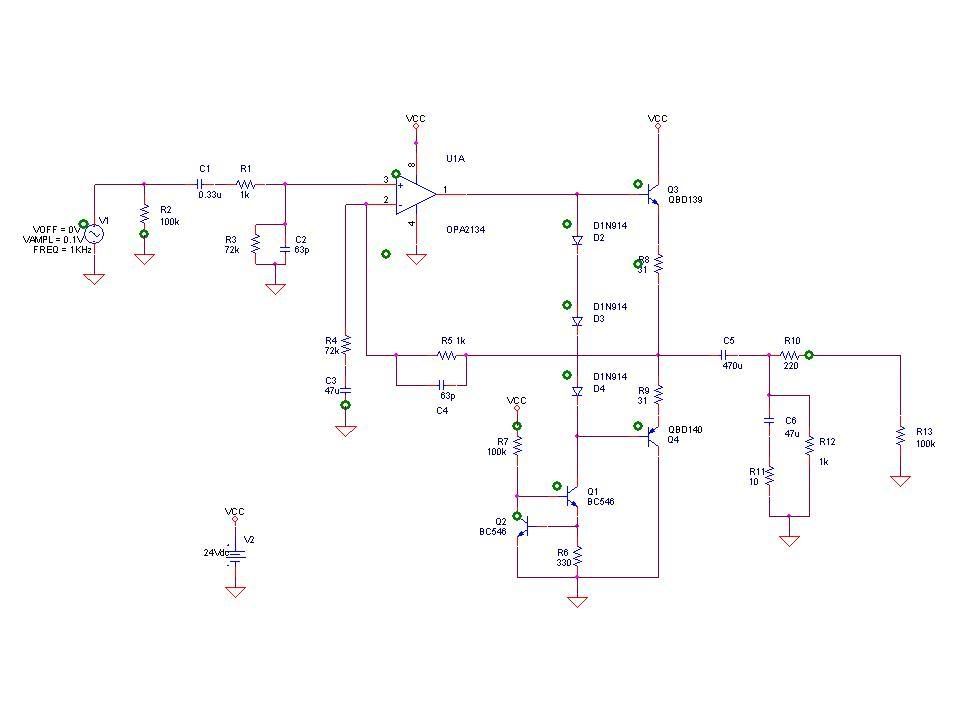
Look at the circuit. Is it a hopeless circuit? Is it the negative feedback cause this problem? How can I tune it to swing higher than +-5V, like +-10V.
Thank you for you reading. I appreciate your reply.
I need more eduacation from you.
I just measured the Vin Vout of this headphone amp. I don't like the performance of it. I have a 300Ohm resistor as a load at the output. I captured the curve of voltage drop on this resistor. Please look at the curve. Input is 1KHz sin wave.
The output voltage saturates at +-5V, as the red line indicates. What cuases this problem? Is it from the OPA saturation? I have a powerful DC source, 24V 3A, so I don't think it is the problem of DC supply.
The other problem is that it is pretty slow. It takes 10 nS swich from -5V to 5V. Is it the slew rate 1V/1uS? This number dispoints me. The C2kIII have 70V/us.
Look at the circuit. Is it a hopeless circuit? Is it the negative feedback cause this problem? How can I tune it to swing higher than +-5V, like +-10V.
Thank you for you reading. I appreciate your reply.