Need help getting started with first CMOY
Mar 22, 2005 at 4:19 PM Thread Starter Post #1 of 21

Rodent

100+ Head-Fier
Joined
Dec 25, 2003
Posts
327
Likes
10
Hi, I've got all the parts listed in tangent's guide, but I could not get tha same protoboard that he uses, and therefore I have a hard time getting started with my CMOY.
His board looks like this;
mini-cmoy--150-board-w-jumpers.jpg


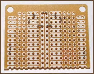
while mine looks like this,
kort.jpg


Could anyone help me and tell me how I should do to make my board work with this?
Your help is much appreciated!
 
Mar 22, 2005 at 9:22 PM Post #3 of 21
But is there nowhere that stocks those protoboards??

I've tried a web search of RS, CPC, Farnell, Maplin and Rapid in the UK.

Nothing.

Just finished a WNA headamp (very good) but would also like to build some CMOY's and using stripboard is not very space efficient.
 
Mar 22, 2005 at 9:39 PM Post #4 of 21
can I take a knife and cut the traces to make it look like that protoboard?
and then I'll have to connect some traces too, right?
 
Mar 23, 2005 at 3:05 PM Post #7 of 21
Rodent,

You could take the protoboard that you have, rotate it 90 degrees (so the connected 3 hole pads are horizontal), and modifyTangent's layout to fit your board, rather than cutting traces, etc. in order to try to make your board look like the ratshack one. You will need to pay special attention to what connects to what in the schematic and in tangent's layout. The ratshack boards are really crap (thin copper, etc.) and aren't really worth pursuing.

You will unfortunately have to cut traces where the opamp is placed (it would appear). The board that you have would I think be very good for discrete components, but not so good for DIP ICs.
 
Mar 23, 2005 at 11:30 PM Post #8 of 21
Hi, thanks. I think I'll just rotate it like you said and cut some traces to make it look like the board in the guide, figure it'll be easier in a way, since im new to this.
What do you mean with "cut traces where the opamp is placed"?

Some of the rows on his protoboard only have two holes that are connected, but I dont need to cut traces to the third hole to make it work, right? Shouldnt matter as long as I dont use the 3rd hole, or am I lost here?
 
Mar 28, 2005 at 12:17 PM Post #10 of 21
Okay, I've cut some traces now, but I wonder which side I should have the components on? Should the side with the traces be faced down, and should I put the components in from the other side? If so, I reversed my board
wink.gif
No biggie though.
 
Mar 29, 2005 at 7:31 PM Post #12 of 21
Hey Rodent - I'm about to embark on my first Cmoy too. Did you get anywhere with your tripad stripboard - I can't find the 'recommended' tangent part either, and I'm trying to get my head around the design on either a 3-hole pad or a 'single track across the row' type board.
 
Mar 29, 2005 at 8:09 PM Post #13 of 21
Quote:

mini-cmoy--150-board-w-jumpers.jpg


I have no comment other than to say that the pencil pictured above (Zebra M-504 0.5mm mechanical pencil) is simply the best mechanical pencil ever! I've had the same one since September '00. In April 02' I discovered a simple mod that greatly increased its aesthetic appeal as well as mass distribution; remove the pocket clip by removing the cap, unscrewing the top and lifting off the ring. I have 5 of these unopened in storage just in case the company ever goes out of business. That should be enough for at least 25 years.
 
Mar 31, 2005 at 10:39 PM Post #14 of 21
Quote:

Originally Posted by FranzMaas
Hey Rodent - I'm about to embark on my first Cmoy too. Did you get anywhere with your tripad stripboard - I can't find the 'recommended' tangent part either, and I'm trying to get my head around the design on either a 3-hole pad or a 'single track across the row' type board.


nope, this was the best fitting board I could find. anyway, i modified it so its the same as the one in the guide now.

could anyone answer my last question?
smily_headphones1.gif
 
Mar 31, 2005 at 11:07 PM Post #15 of 21
Quote:

Originally Posted by Rodent
Okay, I've cut some traces now, but I wonder which side I should have the components on? Should the side with the traces be faced down, and should I put the components in from the other side? If so, I reversed my board
wink.gif
No biggie though.


Yes, components would go in from the non-copper side. This will give you better solder connection/mechanical stability. If you do it the other way, forces can pull the copper pads off the board.
 

Users who are viewing this thread

Back
Top